Installation 2
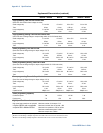
Series N6700 User’s Guide 33
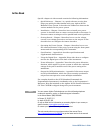
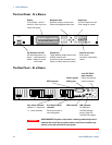
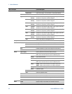
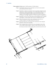
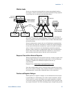
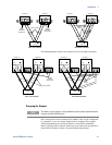
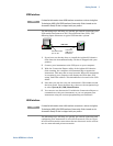
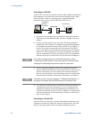
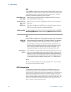
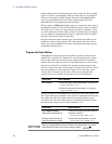
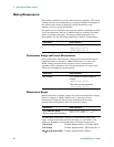
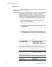
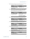
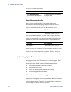
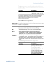
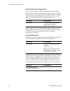
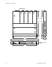
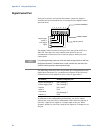
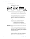
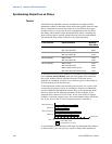
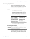
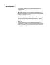
The following figure shows the connections for 50A power modules.
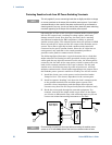
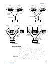
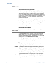
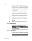
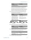
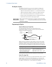
Setting the Outputs
Outputs connected together in series cannot be grouped.
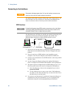
To program outputs connected in series, first program the current
limit of each output to the total desired current limit point. Then
program the voltage of each output so that the sum of both voltages
equals the total desired operating voltage. The simplest way to
accomplish this is to program each output to one half of the total
desired operating voltage.
NOTE
The operating mode of each output is determined by the output’s programmed
settings, operating point, and load condition. Because these conditions may
change during series operation, the front panel status indicator will reflect
these changes. This is normal. Momentary status changes are also normal.
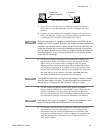
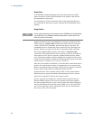
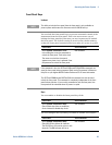
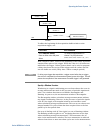
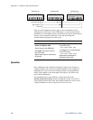
OUTPUT 2
OUTPUT 1
+S + -S
+S + -S
WITH REMOTE SENSING
SENSE
JUMPER
INSTALLED
OUTPUT 2
OUTPUT 1
+S + -S
TWIST LEADS
LOAD
+S + -S
WITH LOCAL SENSING
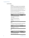
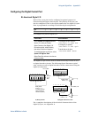
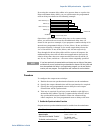
+
TWIST LEADS
SENSE
JUMPERS
INSTALLED
SENSE
JUMPERS
INSTALLED
LOAD
+
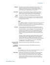
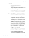
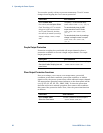
WITH LOCAL SENSING WITH REMOTE SENSING
SENSE
JUMPERS
INSTALLED
LOAD
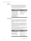
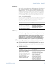
OUTPUT 1OUTPUT 3
LOAD
+
SENSE
JUMPER
INSTALLED
TWIST LEADS
+
TWIST LEADS
++
+S +LS -LS -S
OUTPUT 1OUTPUT 3
++
+S +LS -LS -S
+S +LS -LS -S
+S +LS -LS -S