


Series N6700 User’s Guide 89
Appendix B
Using the Digital Port
Digital Control Port ...........................................................................................90
Configuring the Digital Control Port...............................................................91
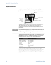
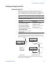
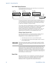
A Digital Control Port consisting of seven I/O pins is provided to
access various control functions. Each pin is user-configurable. The
following control functions are available for the I/O pins:
Bi-directional Digital I/O
Digital Input only
External Trigger
Fault Output
Inhibit Input
Output State (see Appendix D)
NOTE
Earlier Agilent N6700A mainframes use a 4-pin connector instead of the 8-pin
connector available on the N6700B, N6701A, and N6702A mainframes. Refer to
the Service Guide for information on pin functionality of the 4-pin connector.