


2 Installation
30 Series N6700 User’s Guide
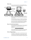
Open Sense Leads
The sense leads are part of the output's feedback path. Connect them
in such a way so that they do not inadvertently become open
circuited. The power system includes protection resistors that reduce
the effect of open sense leads during remote-sensing operation. If the
sense leads open during operation, the power system returns to the
local sensing mode, with the voltage at the output terminals
approximately 1% higher than the programmed value.
Over-voltage Protection Considerations
The OVP circuit senses at the main output terminals and not through
the sense terminals. Due to the voltage drop in the load leads, the
voltage sensed by the OVP circuit could be higher than the voltage
being regulated at the load. Therefore, you must take into account the
additional voltage drop in the load leads when setting the over-
voltage trip point.
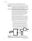
Output Noise Considerations
Any noise picked up on the sense leads will appear at the output
terminals and may adversely affect CV load regulation. Twist the
sense leads or use a ribbon cable to minimize the pickup of external
noise. In extremely noisy environments it may be necessary to shield
the sense leads. Ground the shield at the power system end only; do
not use the shield as one of the sensing conductors.
The noise specifications in Appendix A apply at the output terminals
when using local sensing. However, voltage transients may be
produced at the load by noise induced in the leads or by load current
transients acting on the inductance and resistance of the load lead. If
it is desirable to keep voltage transient levels to a minimum, place an
aluminum or tantalum capacitor, with an approximate value of 10 µF
per foot (30.5 cm) of load lead, right across the load.
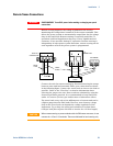
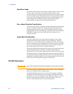
Parallel Connections
CAUTION
Only connect outputs that have identical voltage and current ratings in parallel.
Connecting outputs in parallel provides a greater current capability
than can be obtained from a single output.
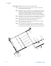
The following figures show how to connect two outputs in parallel.
The figure on the left illustrates local sensing. If voltage drop in the
load leads is a concern, the figure on the right shows how to connect
the sense leads directly at the load. Note that in both cases, the
remote sense terminals must be connected together.