3 Getting Started
40 Series N6700 User’s Guide
Connecting to the Interfaces
CAUTION
Electrostatic discharges greater than 1 kV near the interface connectors may
cause the unit to reset and require operator intervention.
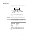
The Agilent N6700 MPS supports GPIB, LAN, and USB interfaces. All
three interfaces are live at power-on. The front panel IO indicator
comes on whenever there is activity on the remote interfaces.
GPIB Interface
NOTE
For detailed information about GPIB interface connections, refer to the Agilent
Technologies USB/LAN/GPIB Interfaces Connectivity Guide, located on the
Automation-Ready CD that is shipped with your product.
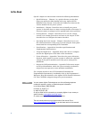
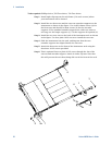
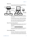
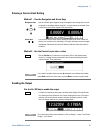
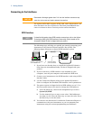
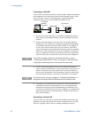
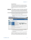
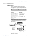
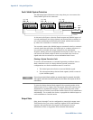
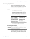
The following steps will help you quickly get started connecting your
instrument to the General Purpose Interface Bus (GPIB). The
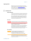
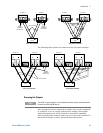
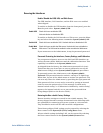
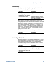
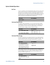
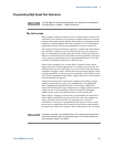
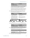
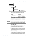
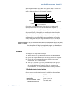
following figure illustrates a typical GPIB interface system.
1 If you have not already done so, install the Agilent IO Libraries
Suite from the Automation-Ready CD that is shipped with your
product.
2 If you do not have a GPIB interface card installed on your
computer, turn off your computer and install the GPIB card.
3 Connect your instrument to the GPIB interface card using a GPIB
interface cable.
4 Use the Connection Expert utility of the Agilent IO Libraries
Suite to configure the installed GPIB interface card’s parameters.
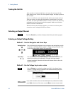
5 The power system is shipped with its GPIB address set to 5. Use
the front panel menu if you need to change the GPIB address.
a Press the Menu key, then use the navigation keys to select
System\IO\GPIB.
b Use the numeric keys to enter a new value. Valid addresses
are from 0 to 30. Press the Enter key to enter the value. Press
the Meter key to exit the menu.
6 You can now use Interactive IO within the Connection Expert to
communicate with your instrument, or you can program your
instrument using the various programming environments.
PC
Instrument
GPIB Cable
Connect to GPIB Interface
Card installed in PC.
Instrument
Connect to GPIB
port on instrument.