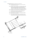
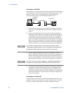
Appendix B Using the Digital Port
92 Series N6700 User’s Guide
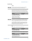
Digital Input
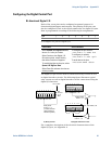
Each of the seven pins can be configured as digital input only. The
polarity of the pins can also be configured. Pin 8 is the signal
common for the digital input pins. The pin status reflects the true
condition of the external signal that is applied to the pin. The pin
state is not affected by the value of the digital output word.
To configure the pins for digital input only:
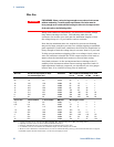
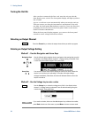
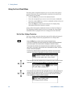
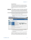
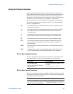
Front Panel: SCPI Command:
Select System\IO\DigPort\Pin<n>,
where <n> is the pin number.
Select Function, then Digital In.
Go back one level, select Polarity,
then either Positive or Negative.
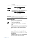
To read the data from the pins, select
System\IO\DigPort\Data.
The input data is displayed as a binary
number in the Data In field.
To configure the pin function:
DIG:PIN<1-7>:FUNC DINP
To configure pin polarity:
DIG:PIN<1-7>:POL <pol>
To read the pin data:
DIG:INP:DATA?
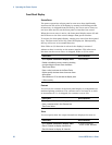
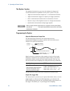
External Trigger
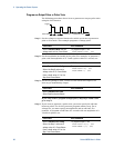
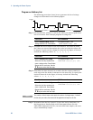
Each of the seven pins can be configured as either trigger inputs or
trigger outputs. The polarity of the pins can also be configured. When
you program trigger polarity, POSitive means a rising edge and
NEGative means a falling edge. Pin 8 is the signal common for the
trigger pins.
When configured as a trigger input, you can apply either a negative-
going or a positive-going pulse to the designated trigger input pin.
The trigger latency is 5 microseconds. The minimum pulse width is 4
microseconds for positive-going signals, and 10 microseconds for
negative-going signals. The pin’s polarity setting determines which
edge generates a trigger-in event.
When configured as a trigger output, the designated trigger pin will
generate a 10 microsecond-wide trigger pulse in response to a trigger
event. Depending on the polarity setting, it can be either positive-
going or negative-going when referenced to common.
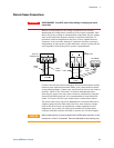
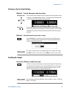
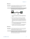
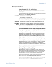
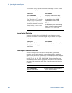
Front Panel: SCPI Command:
Select System\IO\DigPort\Pin<n>,
where <n> is the pin number.
Select Function, then either
Trigger In or Trigger Out.
Go back one level, select Polarity,
then either Positive or Negative.
To select the trigger output
function for pin 1:
DIG:PIN1:FUNC TOUT
To select the trigger input function
for pin 2:
DIG:PIN2:FUNC TINP
To select the trigger polarity:
DIG:PIN<1-7>:POL <pol>