Appendix D Output On/Off Synchronization
104 Series N6700 User’s Guide
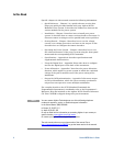
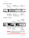
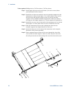
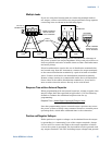
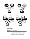
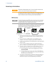
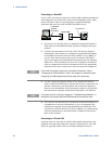
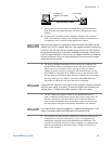
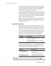
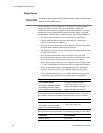
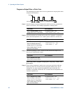
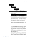
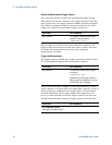
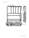
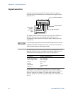
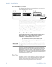
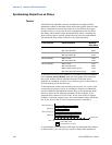
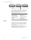
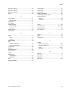
Only two of the digital connector pins on each mainframe can be
configured as “ONCouple” and “OFFCouple” on each synchronized
mainframe. The designated pins will function as both an input and an
output, with a negative transition on one pin providing the
synchronization signal to the other pins.
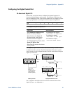
Front Panel: SCPI Command:
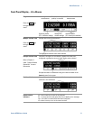
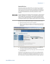
For mainframe #1, select
System\IO\DigPort\Pin6
Select Function, then ONCouple.
Select Pin7, then select Function,
then OFFCouple.
Repeat these steps for mainframes
#2 and #3.
To configure pin 6 of mainframe #1
as the ON control:
DIG:PIN6:FUNC ONC
To configure pin 7 of mainframe #1
as the OFF control:
DIG:PIN7:FUNC OFFC
Repeat these commands for
mainframes #2 and #3.
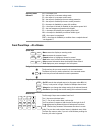
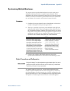
Operation
Once configured and enabled, turning the output on or off on any
coupled channel will cause all coupled channels on all configured
mainframes to turn on or off according to their user-programmed
delays. This applies to the front panel On/Off key, the Web server,
and to SCPI commands.
If a mainframe has its ON/OFF key coupled (located in the
System\Preferences\Keys menu), turning the output on or off on
any coupled channel will cause all coupled channels as well as non-
coupled channels on that mainframe to turn on or off.
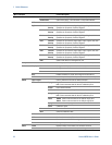
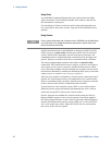
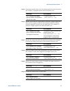
Common
1 2 3 4 5 6 7
I
1 2 3 4 5 6 7
I
1 2 3 4 5 6 7
I
Mainframe #1 Mainframe #2 Mainframe #3
ON Couple
OFF Couple