


Specifications
1-6
TDS5000B Series Specifications and Performance Verification
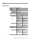
Specification Tables
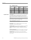
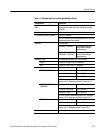
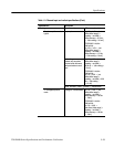
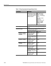
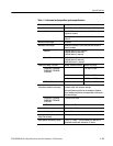
Table 1-2: Channel input and vert ical specifications
Characteristic Description
Input coupling AC, DC, and GND
Input channels
TDS5034B, TDS5054B,
TDS5054BE, TDS5104B
Four i dentical channels
TDS5032B, TDS5052B Two identical channels
Input impedance selection 50 Ω or 1 MΩ.
TDS5104B bandwidth limited to 500 MHz, 1 MΩ selected
Input impedance, DC coupled Product Limits
50 Ω,typical TDS5032B, TDS5052B,
TDS5034B, TDS5054B,
TDS5054BE
±1.0%
TDS5104B ±2.5%
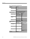
VSWR TDS5032B, TDS5034B ≤1.6:1 t ypical from DC to
350 MHz
TDS5052B, TDS5054B,
TDS5054BE
≤1.6:1 t ypical from DC to
500 MHz
TDS5104B ≤1.5:1 t ypical from DC to
1GHz
1MΩ TDS5032B, TDS5052B,
TDS5034B, TDS5054B,
TDS5054BE
±1.0% i n parallel with
15.5 pF ±2pF
TDS5104B ±1.0% i n parallel with
18 pF ±2pF
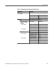
Maximum v oltage at input BNC AC, DC, or GND coupled
1MΩ 150 V
RMS
CAT I, and ≤400 peak
For st eady state sinusoidal waveforms, derate at
20 dB/decade above 200 kHz to 9 V
RMS
at ≥3MHz
50 Ω TDS5032B, TDS5052B,
TDS5034B, TDS5054B,
TDS5054BE
5V
RMS
with peaks less
than ±30 V
TDS5104B <1 Vrms for settings be-
low 100mV/div
<5 Vrms for 100 mV/div
settings and above