Brief Procedures
TDS5000B Series Specifications and Performance Verification
2-9
H Average mode displays an actively acquiring waveform on-screen with
the noise reduced.
H Envelope mode displays an actively acquiring waveform on-screen with
the noise displayed.
H WMFDB Mode displays an actively acquiring waveform on-screen with
noise. All channels will change to a red color.
8. Test all channels: Repeat steps 2 through 7 until all input channels are
verified.
9. Remove the test hookup: Disconnect the probe from the channel input and
the probe compensation output.
Equipment
required
One 10X oscilloscope probe, such as Tektronix P5050
Prerequisites None
1. Initialize the oscilloscope: Push the front-panel DEFAULT SETUP button.
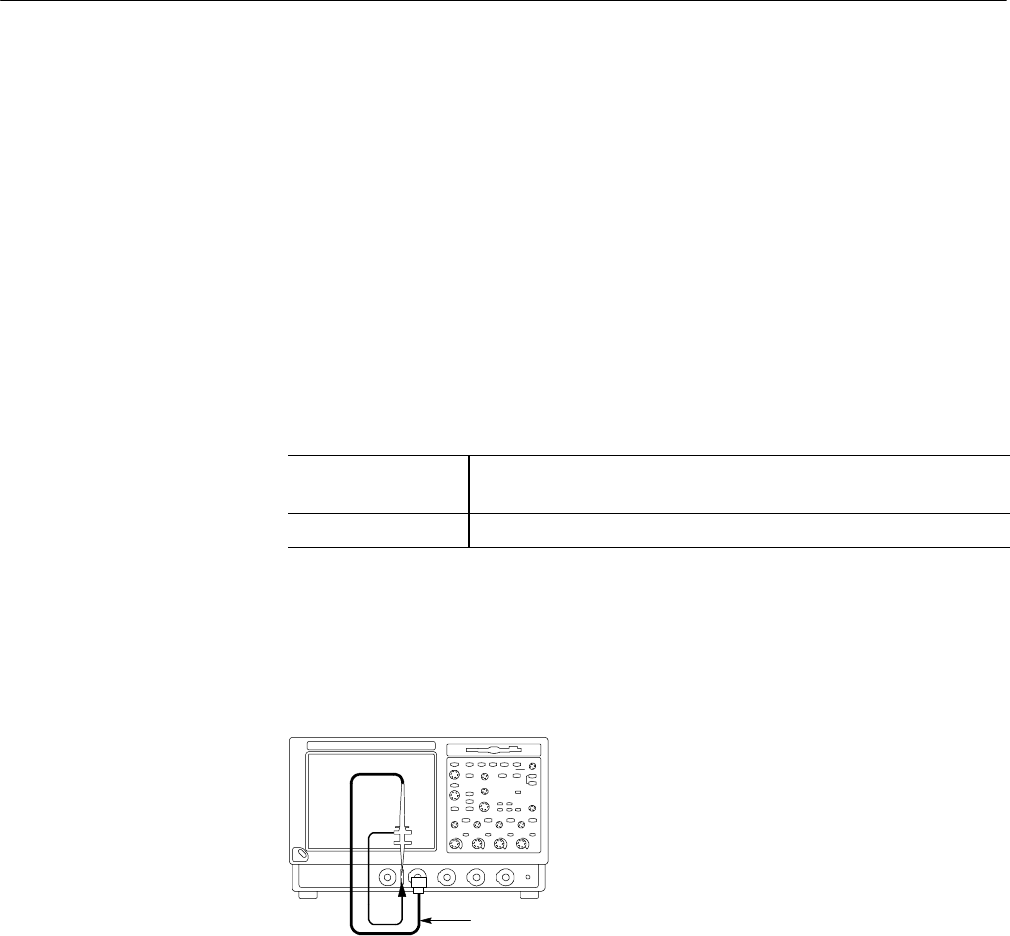
2. Hook up the signal source: Connect the probe to the probe compensation
output and to the C H 1 input as shown in Figure 2--4.
TDS5000B Series oscilloscope
Probe from PROBE
COMPENSATION
outputto CH 1input
Figure 2- 4: Setup for time base test
3. Set up the oscilloscope: Push the front panel AUTOSET button.
4. Set the time base: Set the horizontal SCALE to 200 s/div. The time-base
readout is displayed at the bottom of the graticule.
5. Verify that the time base operates: Confirm the following statements.
H One period of the square-wave probe-compensation signal is about five
horizontal divisions on-screen for the 200 s/div horizontal scale setting.
Verify the Time Base


