


Specifications
1-16
TDS5000B Series Specifications and Performance Verification
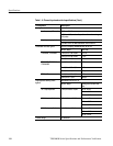
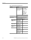
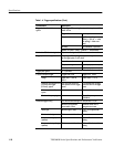
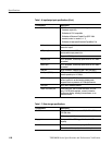
Table 1-4: Trigger specifications (Cont.)
Characteristic Description
Trigger level or threshold accuracy,
typical
Edge trigger, DC coupling, for signals having rise and fall
times ≤20 ns
Trigger Source Accuracy
Any channel ± [(2% ×| setting -- net
offset |) + (0.3 div × volts/
div setting) + offset accu-
racy]
Auxiliary Not calibrated or specified
Where, net offset = offset -- (position × volts/division)
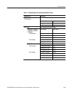
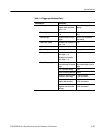
Set level to 50% function, typical Operates with signals ≥30 Hz
Trigger posit ion error, typical Edge trigger, DC coupling, for signals having a slew rate
at the trigger point of ≤0.5 div/ns
Acquisition mode Error
Sample, Average ± (1 displayed pt + 1 ns)
Envelope ± (2 displayed pt s + 1 ns)
Trigger jitter, typical σ = 8 ps RMS
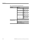
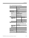
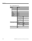
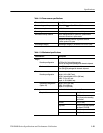
B Event (Delayed) trigger Trigger After Time Trigger on n
th
Event
Range Delay time = 16 ns to
250 s
Event count = 1 to 10
7
Minimum time between arm
(A Event) and trigger
(B Event ), typical
2 ns from the end of the
time period to the B trigger
event
2 ns between the A trigger
event and the first B trigger
event
Minimum pulse widt h,
typical
— B event width ≥1ns
Maximum frequency, typical — B event frequency
≤500 MHz
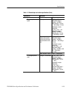
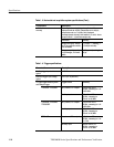
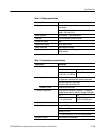
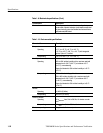
Advanced trigger timing For vertical scale settings ≥10 mV/div and ≤1V/div
Minimum recognizable
event widt h or time
Minimum rearm time to
recognize next event
Glitch type Minimum glitch width = 1 ns 2 ns + 5% of glitch width
setting
Runt or window type Minimum runt width = 2 ns 2ns
Runt or window type (time
qualified)
Minimum runt width = 2 ns 8.5 ns + 5% of runt width
setting
Runt or window type (logic
qualified)
Minimum runt width = 2 ns 8.5 ns + 5% of runt width
setting