


Performance Tests
TDS5000B Series Specifications and Performance Verification
2-33
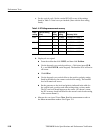
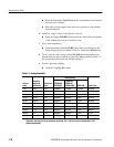
i. Check remaining vertical scale settings against limits (optional):
H If desired, finish checking the remaining vertical scale settings for
the channel under test by repeating substeps d through h for each of
the remaining scale settings listed in Table 2--3 for the channel under
test.
H Before doing substep f, click the Clear button to remove the
previous channel measurements.
H When doing substep f, skip the subparts that turn on the CH<x>
Pk-Pk measurement until you check a new channel.
H Install/remove attenuators between the generator leveling head and
the channel input as needed to obtain the six division reference
signals listed in the table.
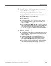
j. Test all channels: Repeat substeps a through h for all channels.
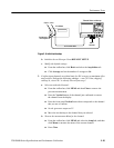
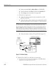
3. Disconnect the hookup: Disconnect the test hook up from the input
connector of the channel last tested.
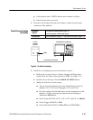
Equipment
required
One sine wave generator (Item 13)
Three precisi on 50 Ω coaxial cables (Item 4)
One power divider (Item 15) or dual input coupler (item 7)
3 SMA female to female adapter connector (Item 16)
3 SMA male-to-female BNC adapter connector (Item 17)
Prerequisites Read Prerequisit es on page 2--17 and foot note warnings on page 2--19.
STOP. Do not use the vertical position knob to reposition any channel while
doing this check. To do so invalidates the test.
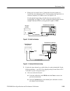
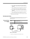
1. Install the test hookup and preset the instrument controls:
a. Initialize the front panel: Press the DEFAULT SETUP button.
b. Modify the initialized front-panel control settings:
H Do not adjust the vertical position of any channel during this
procedure.
H From the toolbar, click the Vert button.
H Set the termination of each channel to 50 Ω by selecting each
channel tab and clicking the Termination 50 Ω button.
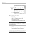
Check Delay Bet ween
Channels