


Performance Tests
2-24
TDS5000B Series Specifications and Performance Verification
Signal Acquisition System Checks
The following procedures verify those characteristics that relate to the signal-ac-
quisition system and are listed as checked under Warranted Characteristics in
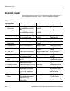
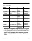
the Specifications section. Refer to Table 2--1 on page 2--18 for test equipment
specifications.
NOTE. References to CH 3 and CH 4 apply to the TDS5034B, TDS5054B,
TDS5054BE, and TDS5104B models only.
WARNING. The generator is capable of outputting dangerous voltages. Be sure to
set the DC calibration generator to off or 0 volts before connecting, disconnect-
ing, and/or moving the test hookup during the performance of this procedure.
Also, verify that the calibrator does not have shorting straps installed between
the DC and sense outputs or grounds.
Equipment
required
Two dual-banana connectors (Item 5)
One BNC T connector (Item 6)
One DC calibration generator (Item 10)
Two precision 50 Ω coaxial cables (Item 4)
Prerequisites The oscilloscope must meet the prerequisites listed on page 2--17.
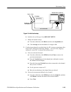
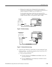
1. Install the test hookup and preset the instrument controls:
a. Hook up the test-signal source:
H Set the output of a DC calibration generator to off or 0 volts.
H Connect the output of a DC calibration generator through a
dual-banana connector followed by a 50 Ω precision coaxial cable to
one side of a BNC T connector. See Figure 2-- 8.
H Connect the Sense output of the generator through a second
dual-banana connector followed by a 50 Ω precision coaxial cable to
the other side of the BNC T connector. Now connect the BNC T
connector to CH 1. See Figure 2--8.
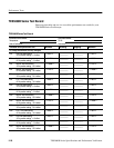
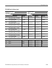
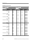
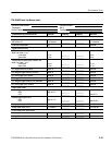
Check DC Voltage
Measurement A ccuracy