


Performance Tests
TDS5000B Series Specifications and Performance Verification
2-39
n. Move the signal to the CH 3 input connector, and then change the
Trigger S OURCE to CH 3 (TDS5034B, TDS5054B, TDS5034BE, or
TDS5104B).
o. C heck — Amplitude of each trace other than CH 3 is 0.16 division or
less (discount trace width). Enter the amplitude in the test record.
p. Move the signal to the CH 4 input connector, and then change the
Trigger S OURCE to CH 4 (TDS5034B, TDS5054B, TDS5054BE, or
TDS5104B).
q. Check — Amplitude of each trace other than CH 4 is 0.16 division or
less (discount trace width). Enter the amplitude in the test record.
3. Disconnect the hookup: Disconnect the cable from the generator output at
the input connector of the channel.
Time Base System Checks
The following procedures verify those characteristics that relate to the time base
system and are listed as checked under Warranted Characteristics in the
Specifications section.
Equipment
required
One tim e-m ark generator (Item 12), or
Sine wave generator (Item 13)
One 50 Ω, precision coaxial cable (Item 4)
Prerequisites Read Prerequisit es on page 2--17 and foot note warnings on page 2--19.
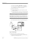
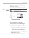
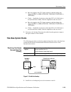
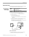
TDS5000B Series oscilloscope
50 Ωcoaxial cable
Output
Time Mark or
Sine Wave
Generator
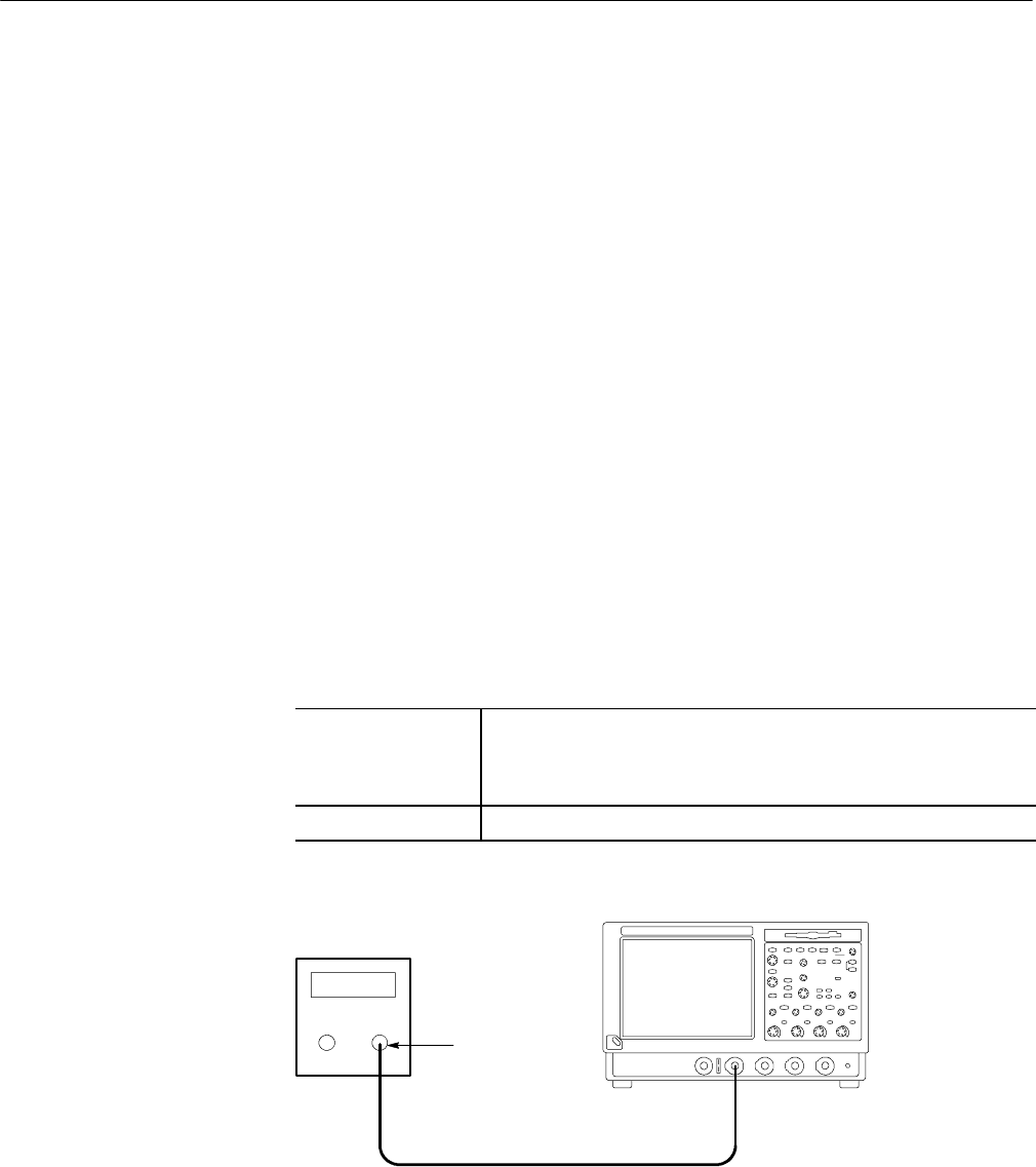
Figure 2- 16: Initial test hookup
1. Install the test hookup and preset the instrument controls:
Check Long-Term Sample
Rate and Delay Time
Accuracy