Performance Tests
TDS5000B Series Specifications and Performance Verification
2-29
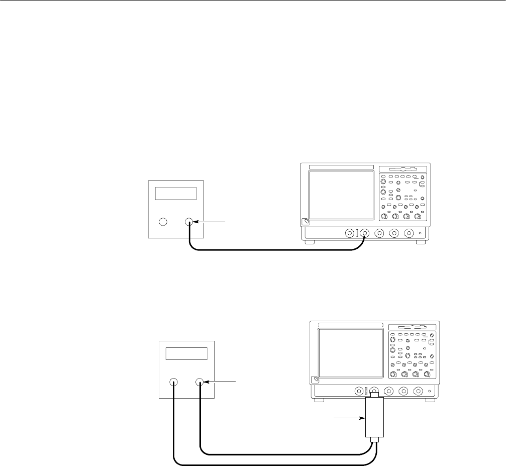
c. Hook up the test-signal source: Connect the sine wave output of a
leveled sine wave generator to CH 1. Set the output of the generator to a
reference frequency of 10 MHz or less. See Figure 2--10.
For the optional setup using a leveled sine wave generator with a
leveling head, see F igure 2--11 and, if using this optional setup with the
example Tektronix SG504, set the generator output to 6 MHz.
TDS5000B Series oscilloscope
Sine wave
generator
Output
50 Ωcoaxial cable
Figure 2- 10: Initial test hookup
TDS5000B Series oscilloscope
High frequency sine
wave generator
Output
Leveling head
50 Ωcoaxial cables
Figure 2- 11: Optional initial test hookup
2. Confirm the input channels are within limits for analog bandwidth: Do the
following substeps — test CH 1 first, skipping substeps a and b since CH 1
is already set up for testing from step 1.
a. Select an unchecked channel:
H From the toolbar bar, click MEAS and then Clear to remove the
previous measurement.
H Press the Vertical button of the channel just confirmed to remove
the channel from the display.


