Performance Tests
2-26
TDS5000B Series Specifications and Performance Verification
c. Set the vertical scale: Set the vertical SCALE to one of the settings
listed in Table 2--2 that is not yet checked. (Start with the first setting
listed.)
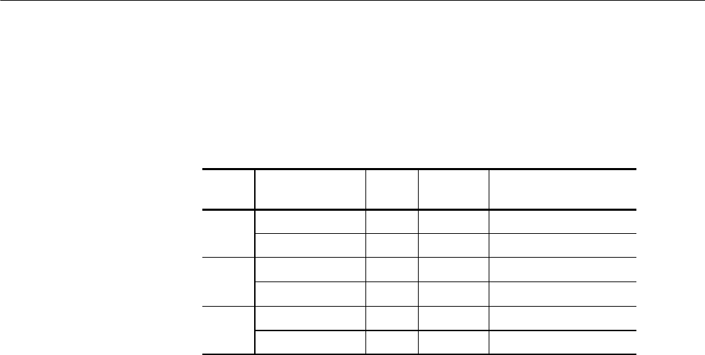
Table 2-2: DC Voltage m easurement accuracy
Scale
setting
Position setting
(Divs)
Offset
setting
Generator
setting
Accuracy limits
5mV -- 5 +1 V +1.040 V +1.0353 V to +1.0447 V
+5 -- 1 V --1.040 V --1.0447 V t o --1.0353 V
200 mV -- 5 +10 V +11.6 V +11.4989 V to +11.7011 V
+5 -- 10 V -- 11. 6 V --11.7011 V to --11.4989 V
1.01 V -- 5 +10 V +18 V +17.602 V to +18.398 V
+5 -- 10 V -- 1 8 V --18.398 V to --17.602 V
d. Display the test signal:
H From the toolbar bar click VERT, and then click Position.
H Use the keypad to set vertical position to --5 divisions (press CLR ,
5, -- ,andthenENTER, on the keypad). The baseline level will move
off screen.
H Click Offset.
H Use the keypad to set vertical offset to the positive-polarity setting
listed in the table for the current vertical scale setting. The baseline
level will remain off screen.
H Set the generator to the level and polarity indicated in the table for
the vertical scale, position, and offset settings that you have made.
The DC test level should appear on the screen. (If it doesn’t return,
the DC accuracy check has failed for the current vertical scale setting
of the current channel.)
e. Measure the test signal: Press Close. Read the measurement results at
the Mean measurement readout. See Figure 2--9.


