


Performance Tests
TDS5000B Series Specifications and Performance Verification
2-41
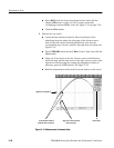
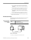
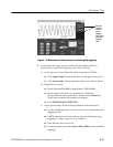
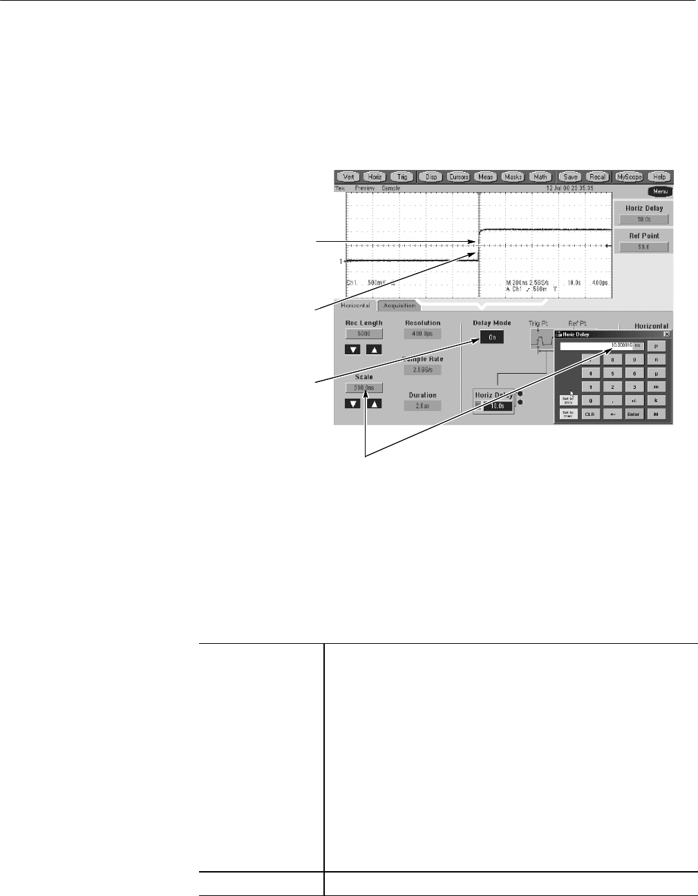
H CHECK that the rising edge of the marker (or sine wave) crosses
the center horizontal graticule line at a point within ±1.5 divisions of
the center graticule. See Figure 2--17 on page 2--41.
H Enter the number of divisions in the test record.
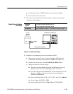
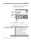
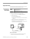
Check long-term
sample rates and
delay time accuracies
against limits.
4
Align the trigger T
to the center
graticule line.
1
Set horizontal mode.
2
Set horizontal scale
and delayedtime.
3
Figure 2- 17: Measurement of accur acy - long-term and delay time
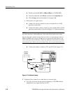
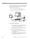
3. Disconnect the hookup: Disconnect the cable from the generator output at
the input connector of CH 1.
Equipment
required
One 50 Ω, precision coaxial cable (Item 4)
One C onnector, BNC “T”, male BNC-to-dual female BNC (Item 6)
One Pulse Generator, Wavetek 9500 or equivalent (Item 18)
Two 50 Ω, coaxial cable, male-to-male SMA connectors (Item 19)
One SMA f emale to BNC male connector (Item 23)
One BNC elbow connector (Item 24)
One SMA “T”, male to two SMA female connectors (Item 22)
Two SMA termination connectors, short circuit (Item 26)
One 2X attenuator, 50 Ω, female BNC-to- male BNC (Item 28)
Prerequisites Read Prerequisit es on page 2--17 and foot note warnings on page 2--19.
Check Delta Time
Measurement A ccuracy