


Performance Tests
2-62
TDS5000B Series Specifications and Performance Verification
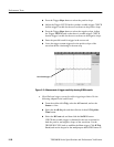
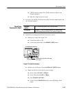
2. Set the Generator:
H Set the sine wave generator to a reference frequency of 10 MHz.
H Adjust the sine wave generator amplitude to the required number of
divisions as measured by the oscilloscope.
3. Record the reference level: Note the reading on the level meter.
4. Set the generator to the new frequency and r eference level:
H Change the sine wave generator to the desired new frequency.
H Input the correction factor and/or the new frequency into the level meter.
H Adjust the sine wave generator amplitude until the level meter again
reads the value noted in step 3. The signal amplitude is now correctly set
for the new frequency for your specific test procedure.
Proceed with the test instructions that require a leveled sine wave generator at
the frequency you set in step 4.
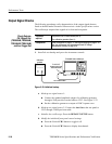
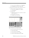
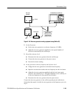
Use this setup if you do not have a power divider.
Equipment
required
Sine wave generator (Item 13)
Level met er and power sensor (Item 14)
Two male N to female BNC adapters (Item 20)
Two precision coaxial cables (Item 4)
Prerequisites Read Prerequisit es on page 2--17 and foot note warnings on page 2--19.
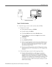
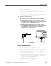
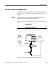
1. Install the test hookup: Connect the equipment as shown in F igure 2-- 29
(start with the s ine wave generator connected to the oscilloscope).
Method B