


Installation
Determining the Test Set to Site Equipment Connections
Chapter 2
O:\Manuals\E6385A_Cdma\Book\Install.fm
36
Determining the Test Set to Site Equipment
Connections
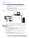
At this point in the process, you must decide the clock reference, the Test Set port, and
the Base Station port to be used in testing. At appropriate points in a test sequence, the
Test Software will display prompts directing you to make connections. For details on the
required connections, see Chapter 3, “Connections,” on page 45.
Which Clock to Use – SCT Clock or External Reference?
If you elect to use the SCT clock signal, connect and enable it as follows:
Step 1. Connect the clock signals (19.6608-MHz and even-second) and transmitter output to the
Test Set (see “Test Set to Base Station Connections” on page 46).
Step 2. Set the TST CLK switch on the SCT module to ON to enable the Base Station clock
signals.
If you elect to use a separate GPS reference instead of the cell site clocks, see “Test Set to
GPS Time and Frequency Reference Receiver Connections” on page 50.
Which Test Set Port to Use – ANT IN or RF IN/OUT?
CAUTION
The Test Set ANT IN port is only used for very low signal levels
≤
60 milliwatts (17.78
dBm). Therefore, to prevent damage to the Test Set, never connect this port directly to the
Base Station TX Antenna Port. This port is typically connected to the Base Station TX
Test Port.
The Test Set RF IN/OUT port is for CDMA signals of
≤15
watts or continuous wave
signals of
≤
75 watts. This is the only port on the Test Set that you should connect directly
to the Base Station TX Antenna Port. If power levels from the Base Station exceed the
specification of the port, use an appropriate signal attenuator.
Which Base Station Port to Use – TX Test or TX Antenna?
Testing may be performed while connected to either the Base Station Test Port or the
Base Station Antenna Port. Testing at the Antenna Port involves taking the Base
Station out of service. The choices are described in the following sections.
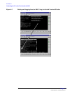
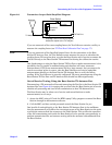
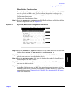
In-Service Testing Using the Base Station TX Test Port
The Base Station TX Test Port signal is derived from the directional coupler that is
connected between the Linear Amplifier and the Base Station TX Antenna Port (see
Figure 2-8). This allows you to make measurements on an active Base Station without
disconnecting the transmit antenna and interrupting service. You must enter a value for
the coupling factor (loss) through the directional coupler to compensate power
measurements (see “Test Configuration” on page 39). Coupling factors are typically 40
to 70 dB, but might vary, depending on the Base Station design.