


Performing Tests
Return Loss Measurement
Chapter 4
83
Performing Tests
Step 5. Press the k1 (Run) key to start the test.
NOTE This procedure might include steps that prompt you to disconnect cables from the site
antenna ports and make connections to the Test Set. Before removing or re-installing the
antenna cables, make certain that the transmitter has been turned off by the MSC (or by
switch personnel). The green ACT LEDs on the ADU and BCR modules indicate that the
transmitter is active, and therefore should be off before disconnecting cables.
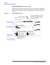
Step 6. At the start of the test sequence, the Test Software will display a connection diagram,
and prompt you to make a connection between the DUPLEX OUT port, ANT IN port of
the Test Set, and the SWR bridge indicated on the on-screen diagram. Press the
k1
(Proceed) key when the connections have been made.
Step 7. The Test Software will turn on the source and makes a reference measurement, then
prompt you to add in the DUT (Device-Under-Test). Connect the DUT to be measured, as
shown in the diagram, and press the
k1 (Proceed) key.
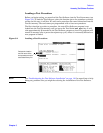
Review the Results
When making a discrete measurement, the Test Software will display the return loss
and VSWR as single numeric values.
When making a swept measurement, the Test Software will display the loss on the
screen (in units of dB) and as a plot of loss versus frequency.
•Pressing the
k5 (Scr Dump) key will cause the Test Software to pause automated
operation. Press the
Print key to send the plot to BTS Laptop Utility program Test Set
Screen Capture window. After the plot has displayed, press the
k2 (Continue) key.
•Pressing the
k1 (Proceed) key will cause the Test Software to display the minimum
and maximum return loss and VSWR measured during the test. From this point, you
may press the
k1 (Repeat) key to test another device, press the k5 (Return) key once
to go to the Return Loss Test setup screen, or press the
k5 (Return) twice to return to
the Test Selections Menu screen.