


Performing Tests
Transmit Power Calibration Test (Autoplex Series II)
Chapter 4
57
Performing Tests
Specifications (Pass/Fail Limits):
• 6. Output Power Adjustment Error. This specification determines where the low and
high tick marks appear on the measurement graphic scale.
Select and Run the Test
Perform the Transmit Power Calibration Test as follows:
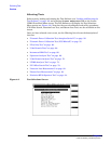
Step 1. From the Lucent CDMA Tests Main Menu screen, select the Test Selections field. The
Test Software will display the Test Selections Menu screen.
Step 2. Select the Transmit Power Calibration field.
Step 3. Follow the displayed instructions and diagram to make the measurement.
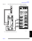
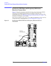
NOTE This procedure might include steps that prompt you to disconnect cables from the site
antenna ports and make connections to the Test Set. Before removing or re-installing the
antenna cables, make certain that the transmitter has been turned off by the MSC (or by
switch personnel if not using a PC). The green ACT LEDs on the ACU and BCR modules
indicate the transmitter is active, and therefore should be off before disconnecting
cables.
Review the Results
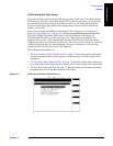
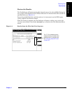
The Test Software will display the power meter screen (see Figure 4-3).
The power meter will display defaults to units of Watts. To view the power level in dBm,
press the
k3 (dBm) key. A beeping tone will accompany the measurement to assist in
adjusting the transmitter power without looking at the display. Adjust the tone volume
by pressing the
k4 (Tns off, Tns quiet, Tns loud) key.
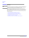
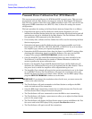
Figure 4-3 Power Meter Display
The longer tick marks
are the high and low
specification limits.
This prompt indicates if
power is low, within
specifications, or high.
These values indicate
the meter high and low
display limits.