


Return to Section TOC Return to Section TOC Return to Section TOC Return to Section TOC
Return to Master TOC Return to Master TOC Return to Master TOC Return to Master TOC
TROUBLESHOOTING & REPAIR
F-49 F-49
RANGER 10-LX
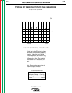
BRUSH REMOVAL AND REPLACEMENT (continued)
PROCEDURE
1. Perform this procedure with the engine
OFF.
2. With the 5/16” and 3/8” nut drivers,
remove the sheet metal screws from the
right case side.
3. Carefully remove the right case side.
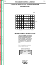
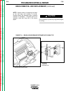
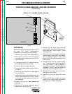
4. Using the needle nose pliers, gently
remove the red and white wires from the
brush holder. Note lead placement. See
Figure F.11.
5. With the 7/16” wrench, remove the brush
holder assembly bracket from the stator
frame.
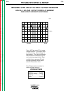
6. With the 5/16” wrench, remove the two
screws that secure the brush holder
assembly to the bracket. Slide the brush
holder assembly out of the bracket.
7. To change the brushes, use the slot head
screw driver to pop off the plastic retainer
on the back of the brush holder assembly.
8. Remove the old brushes and insert the
new ones. One corner of the terminal clip
is beveled so that the brush can go in only
one way.
9. Snap the plastic retainer back onto the
brush holder. The brushes may need
some repositioning; wiggle them slightly to
help them seat properly on the slip rings.
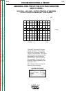
10. To reinstall the brushes, depress the
spring-loaded brushes into the holder and
slip a suitable non-metallic, fairly stiff
retainer through the slots at the top and
bottom of the holder.
11. Slide the brush holder assembly back into
the bracket and, with the 5/16” wrench,
install the two screws that hold it in place.
12. With the 7/16” wrench, install the brush
holder assembly bracket to the stator
frame.,
13. Slowly remove the non-metallic retainer
from the brush holder and let the brushes
snap back against the slip rings.
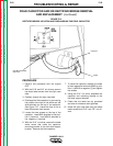
14. With the needle nose pliers, connect the
red and white wires to the appropriate ter-
minals on the brushes. The red wire is
nearest to the rotor lamination.
15. Check the wire connections for clearance
and tightness.
16. Install the right case side using the sheet
metal screws and 5/16” and 3/8” nut
drivers.