


Return to Section TOC Return to Section TOC Return to Section TOC Return to Section TOC
Return to Master TOC Return to Master TOC Return to Master TOC Return to Master TOC
TROUBLESHOOTING & REPAIR
F-67 F-67
RANGER 10-LX
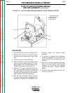
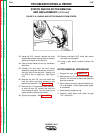
STATOR AND/OR ROTOR REMOVAL
AND REPLACEMENT (continued)
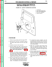
PROCEDURE (Stator Removal)
1. Perform this procedure with the engine
OFF.
2. With the 5/16” and 3/8” nut drivers,
remove the sheet metal screws from the
case top and left and right case sides.
3. If necessary, use the 1/2” wrench to
remove the exhaust pipe from the muffler.
4. Carefully remove the left and right case
sides, then remove the positive (+) lead
from the battery.
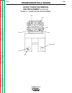
5. Remove the rubber gasket (cover seal)
from the lift bail.
6. Remove the fuel cap and the rubber gasket
from the fill tube.
7. Unlatch the double door assembly and use
the slot head screw driver and 3/8” wrench
to remove the door support rod from the
door assembly.
8. Remove the case top, then reinstall the fuel
cap.
9. With the 1/2” socket wrench, remove the
fuel tank. (Four bolts hold the fuel tank.)
With the 3/8” nut driver, remove lead #226
from the fuel gauge.
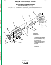
10. With the slot head screw driver, remove the
field bridge rectifier. Leave the leads
attached. Cut any necessary cable ties.
11. Perform the Output Capacitor Bank
Removal procedure.
12. Perform the Brush Removal procedure.
13. Cut the cable ties from the reactor to the
range switch.
14. Remove the four stator leads connected to
the range switch. Use care. Excessive
torgue will break the terminals away from
the rivets.
15. Remove all stator leads from connection
points on the front panel:
Remove lead #31 from circuit breaker CB2.
Disconnect the in-line connector on leads
#42 and #32 located between the stator
and the 14-pin amphenol.
Remove the PC board cover.
Disconnect lead #3 from the 115VAC
receptacle and remove it from the current
sensor located on the control board. It
may be necessary to remove the recepta-
cles.
Disconnect lead #5 from the 115 VAC
receptacle.
Disconnect lead #5D from the common
ground screw.
Disconnect lead #6 from the 115/230 VAC
receptacle.
Disconnect leads #7 and #9 from the field
rectifier bridge (D2). You may have already
done this step when you removed the fuel
tank. Cut any necessary cable ties to free
leads #7 and #9 from the cable bundle.
Remove lead W1 (heavy stator lead) from
the left side output rectifier assembly.
Remove lead S2 (heavy stator lead) from
the left side output rectifier assembly.
Untape and disconnect W2 from S1 to
separate the stator from the reactor.
16. Using the 3/8” wrench, remove the four
screws (2 on each side) holding the output
rectifier assemblies to the base of the
machine.
17. Using the 1/2” wrench, remove the four
choke mounting bolts from the base of the
machine. Push the choke forward, toward
the front of the machine.
18. Perform the Output Contactor Removal
procedure.
19. Remove the heavy lead from the choke to
the bottom of the positive output rectifier.
20. Slide the choke assembly out.
21. Using the 1/2” wrench, remove the three
reactor mounting bolts from the base of
the machine.
22. Using the 5/16” wrench, remove the three
sheet metal screws holding the front verti-
cal baffle.