


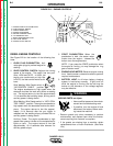
DIESEL ENGINE CONTROLS
See Figure B.2 for the location of the following fea-
tures:
1. GLOW PLUG PUSHBUTTON: Acti-
vates glow plugs to preheat engine for
starting.
2. IDLER CONTROL SWITCH: Adjusts the running
speed of the engine. The switch has two posi-
tions, HIGH and AUTO. In HIGH, the
engine runs continuously at high idle.
In AUTO, the idler control works as fol-
lows:
Stick Welding; Wire Feeder switch in
“NO CONTROL CABLE” position:
The engine accelerates to high speed when the
electrode touches the work and strikes a welding
arc. The engine returns to low idle approximately
10-14 seconds after welding stops, as long as no
auxiliary power is being drawn.
Wire Welding; Wire Feeder switch in “WITH CON-
TROL CABLE” position: The engine accelerates to
high speed when the electrode touches the work-
piece. The engine returns to low idle approxi-
mately 10-14 seconds after the gun trigger is
released and the welding stops, provided that no
auxiliary power is being drawn.
Auxiliary Power: The engine accelerates to high
speed when power is drawn at the receptacles for
lights or tools. The engine returns to low idle
approximately 10-14 seconds after demand for
auxiliary power stops.
3. START PUSHBUTTON: When the
pushbutton is held, the starter motor
cranks over the engine – release the
button once the engine starts.
NOTE: If you press the START pushbutton when
the engine is running, you may damage the ring
gear or starter motor.
4. ENGINE HOUR METER: Records engine running
time. Use the meter to determine when to perform
required maintenance.
5. BATTERY LIGHT: Is off when battery charging
system is functioning normally. If light turns on
while the engine is running, the fan belt may be
broken or the alternator or the voltage regulator
may be defective.
MOVING PARTS can injure.
• Have qualified personnel do mainte-
nanace and troubleshooting work.
• If possible, turn the engine off and
disconnect the battery before work-
ing inside the machine.
• Remove guards only when necessary to perform
maintenance, and replace them when the mainte-
nance requiring their removal is complete.
• If fan guards are missing from a machine, obtain
replacements from a Lincoln Distributor. (See Parts
List.)
OPERATION
B-6 B-6
RANGER 10-LX
Return to Section TOC Return to Section TOC Return to Section TOC Return to Section TOC
Return to Master TOC Return to Master TOC Return to Master TOC Return to Master TOC
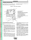
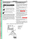
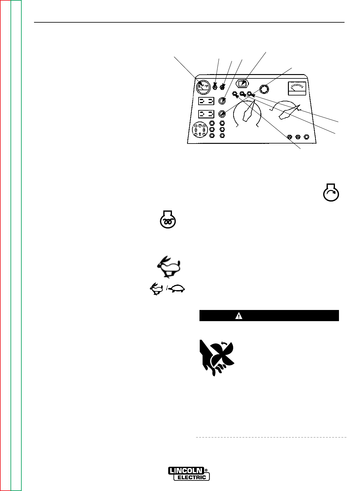
FIGURE B.2 – ENGINE CONTROLS
1. ENGINE GLOW PLUG PUSHBUTTON
2. IDLER CONTROL SWITCH
3. START PUSHBUTTON
4. ENGINE HOUR METER
5. BATTERY CHARGER LIGHT
6. OIL PRESSURE LIGHT
7. WATER TEMPERATURE LIGHT
8. FUEL LEVEL GAUGE
9. ENGINE ON-OFF SWITCH
WARNING
8
2
9
1
4
3
7
6
5