


TROUBLESHOOTING & REPAIR
F-61 F-61
RANGER 10-LX
Return to Section TOC Return to Section TOC Return to Section TOC Return to Section TOC
Return to Master TOC Return to Master TOC Return to Master TOC Return to Master TOC
OUTPUT CAPACITOR BANK EMOVAL
AND REPLACEMENT (continued)
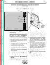
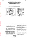
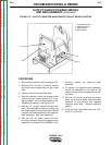
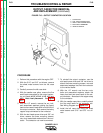
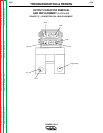
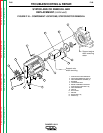
FIGURE F.15 - OUTPUT CAPACITOR BANK/PRINTED CIRCUIT BOARD LOCATION
PROCEDURE
1. Perform this procedure with the engine OFF.
2. WIth the 5/16” and 3/8” nut drivers, remove
the sheet metal screws from the right case
side.
3. Carefully remove the right case side.
4. With the voltmeter, check the voltage across
each of the four output capacitors. If a volt-
age is present, use a 25-watt resistor to dis-
charge each capacitor. See Figure F.15.
5. With the 1/2” wrench, remove the two nuts,
bolts, and associated washers holding the
two heavy leads and two small leads (#242B
negative and #240A positive) to the capacitor
bank buss bars. Note lead placement.
6. With the 3/8” nut driver, remove the four
mounting screws holding the capacitor bank
assembly to the base of the RANGER 10-LX.
7. Carefully remove the capacitor bank
assembly.
8. To replace the capacitor bank assembly,
mount the assembly to the base of the
machine using the four screws and the 3/8”
nut driver.
9. With the 1/2” wrench, attach the two heavy
leads, the two small leads, and associated
fasteners to the positive and negative
capacitor buss bars. Observe capacitor
polarity.
10. Install the right case side using the 5/16”
and 3/8” nut drivers.
1. PC BOARD COVER
2. VERTICAL BAFFLE
3. CAPACITOR (4)
4. BUSS BAR (2)
3
4
2
1