


Return to Section TOC Return to Section TOC Return to Section TOC Return to Section TOC
Return to Master TOC Return to Master TOC Return to Master TOC Return to Master TOC
TROUBLESHOOTING & REPAIR
F-32 F-32
RANGER 10-LX
CHARGING CIRCUIT TEST (continued)
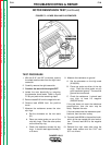
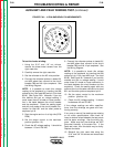
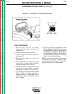
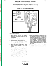
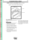
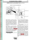
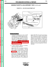
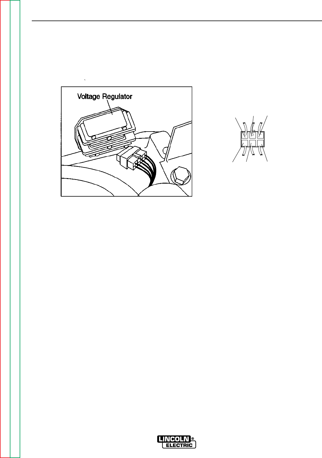
FIGURE F.6 – LOCATION OF VOLTAGE REGULATOR
TEST PROCEDURE
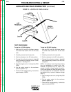
1. With the 5/16” and 3/8” nut drivers,
remove the sheet metal screws from the
left case side.
2. Carefully remove the left case side.
3. Locate the engine alternator and regulator.
See Figure F.6.
4. Start the engine and run it at high idle
(3700 RPM).
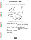
5. Set the voltmeter for AC volts and measure
the AC volts at leads #233 and #234.
Normal is between 22 and 26 VAC.
6. Set the voltmeter for DC volts and measure
the DC volts at leads #222D to lead #5J
(case ground). Normal is 13.5 to 15 VDC.
7. If the correct AC volts are present at leads
#233 to #234, the engine alternator is
operating correctly. If the voltage is low or
missing, the engine alternator may be
faulty. Replace.
8. If the correct AC volts are present at leads
#233 to #234 but the DC volts are incorrect
at leads #222D to lead #5J (case ground),
the regulator may be faulty. Before replac-
ing the regulator, check the wiring from the
regulator to the alternator and the charging
circuit. See the Wiring Diagram.
NOTE: If you test with probes at the plug by
the regulator and you get no reading, check
the wires back to the alternator. The problem
may be in the wiring, not the alternator.
5J
233
234
236
224A 222D