


Return to Section TOC Return to Section TOC Return to Section TOC Return to Section TOC
Return to Master TOC Return to Master TOC Return to Master TOC Return to Master TOC
F-22 F-22
RANGER 10-LX
ROTOR VOLTAGE TEST (continued)
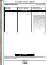
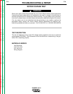
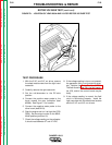
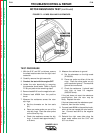
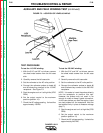
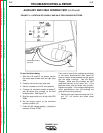
FIGURE F.1 - LOCATION OF LEAD 200A AND 219 FOR ROTOR VOLTAGE TEST
TROUBLESHOOTING & REPAIR
TEST PROCEDURE
1. With the 5/16” and 3/8” nut driver, remove
the sheet metal screws from the right hand
case side.
2. Carefully remove the right case side.
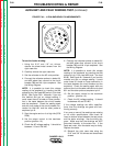
3. Set the volt/ohmmeter to the DC volts
position.
4. Connect the positive meter probe to the
brush nearest the rotor lamination (lead
#200A). See Figure F.1 for location.
5. Connect the negative meter probe to the
other brush (lead #219).
6. Start the engine and run it at high idle (3700
RPM). Set the output control to the MAXI-
MUM position (position 10).
7. Check the voltage reading on the voltmeter.
It should read between 37 and 47 VDC.
8. If the voltage reading is low or not present,
the generator field is not functioning prop-
erly. Perform the Rotor Resistance Test.
The field diode bridge (D2), the field capac-
itor (C2), and/or the control board may be
faulty.
9. If the voltage reading is normal, the field
circuit is functioning properly. Install the
right case side with the sheet metal screws
and the 5/16” and 3/8” nut drivers.