


Return to Section TOC Return to Section TOC Return to Section TOC Return to Section TOC
Return to Master TOC Return to Master TOC Return to Master TOC Return to Master TOC
TROUBLESHOOTING & REPAIR
F-30 F-30
RANGER 10-LX
OUTPUT RECTIFIER BRIDGE TEST (continued)
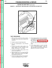
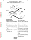
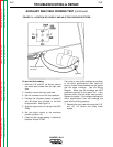
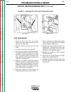
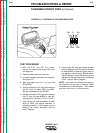
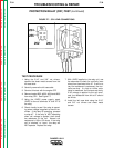
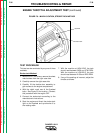
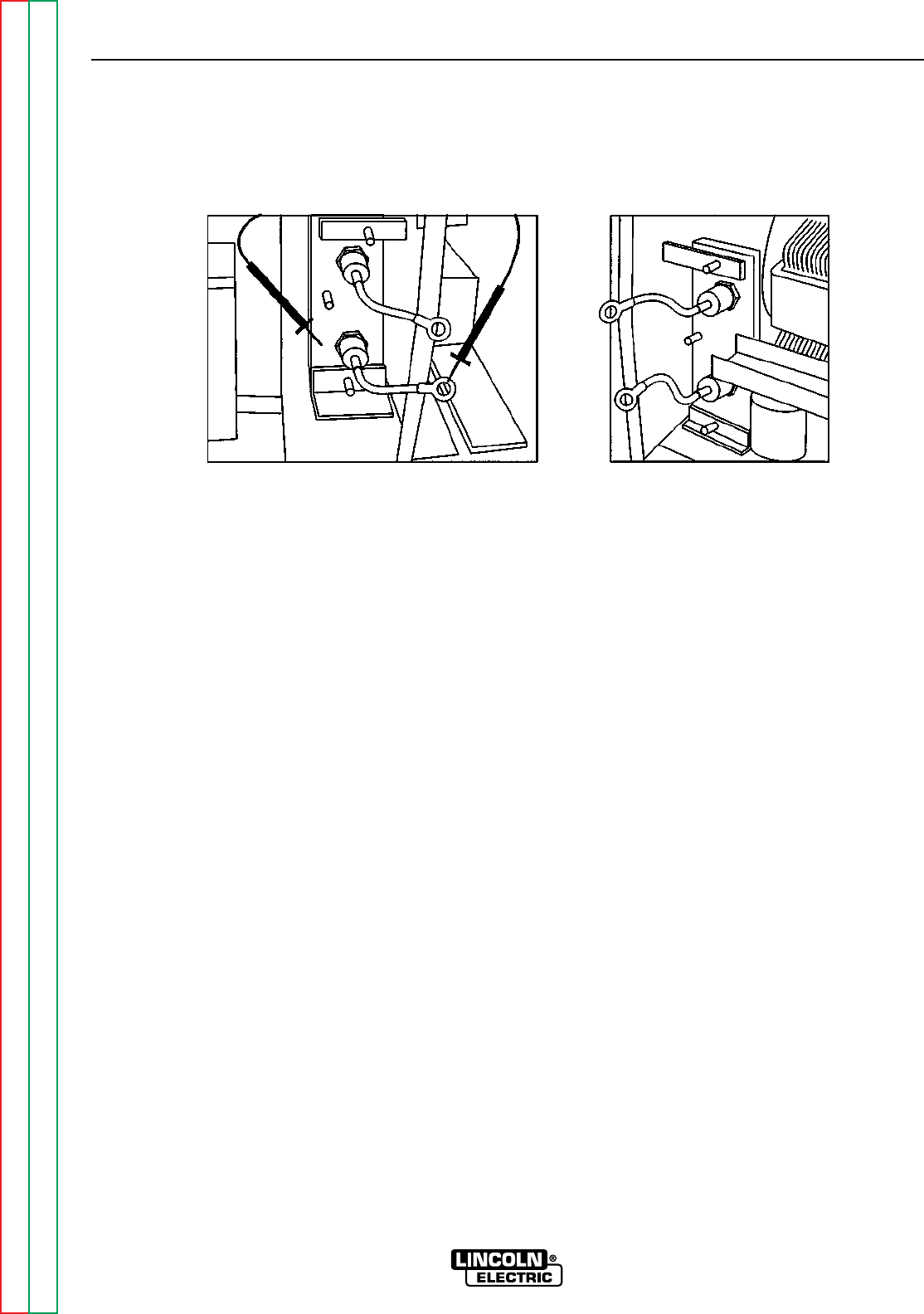
FIGURE F.5 – LOCATION OF OUTPUT RECTIFIER DIODE LEADS
TEST PROCEDURE
1. Using the 5/16” and 3/8” nut drivers,
remove the sheet metal screws from the
right and left case sides.
2. Carefully remove the right and left case
sides.
3. Conduct this test with the engine OFF.
4. Locate the two halves of the output rectifier.
The negative plate is located on the lower
left side of the machine behind the case
front. The positive plate is located on the
lower right side of the machine behind the
case front. See Figure F.5.
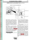
5. With the 1/2” wrench, remove the nuts and
washers holding the diode pigtails and the
heavy current-carrying leads to the studs
located at the tops and bottoms of the rec-
tifier plates. Note their locations and the
order of fasteners for reassembly.
6. Electrically isolate the diode pigtails by
carefully bending them out into “free air.”
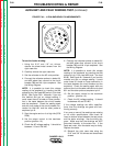
7. With an ohmmeter or diode tester, check
each of the four diodes from their pigtails
to their respective heat sinks.
8. Reverse the tester leads and check the
diodes again. Diodes should have a low
resistance in one polarity and a very high
resistance in the opposite polarity.
9. Replace any “shorted” or “open” diode as
the tests indicate.
10. Reconnect the diode pigtails and heavy
leads to their respective studs.
11. Reinstall the left and right case sides using
the 5/16” and 3/8” nut drivers and sheet
metal screws.
Left side (–)
Right side (+)