


Return to Section TOC Return to Section TOC Return to Section TOC Return to Section TOC
Return to Master TOC Return to Master TOC Return to Master TOC Return to Master TOC
OPERATION
B-4 B-4
RANGER 10-LX
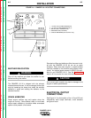
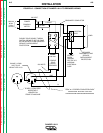
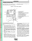
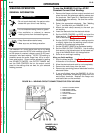
FIGURE B.1 – OUTPUT PANEL CONTROLS
1. OUTPUT RANGE SELECTOR
2. FINE OUTPUT CONTROL
3. POLARITY SWITCH
4. CONTROL AT WELDER/REMOTE CONTROL SWITCH
5. WIRE FEEDER NO CONTROL CABLE/WIRE FEEDER
WITH CONTROL CABLE SWITCH
6 WIRE FEEDER POWER CIRCUIT BREAKER
7. 115 VOLT, 20 AMP RECEPTACLES (2)
8. 115/230 VOLT, 50 AMP RECEPTACLE
9. WELD OUTPUT TERMINAL (TO WORK)
10. WELD OUTPUT TERMINAL (TO ELECTRODE HOLDER)
11. GROUND STUD (LOCATION)
12. 14 PIN AMPHENOL
13. 6 PIN AMPHENOL
14. VOLTMETER
WELDER/GENERATOR CONTROLS
See Figure B.1 for the location of the following fea-
tures:
1. OUTPUT RANGE SELECTOR: Selects continu-
ous current output for constant current stick or
TIG applications (blue settings) and constant volt-
age wire feed applications (white settings). The
amperages on the dial correspond to the maxi-
mum amperages for each corresponding range
setting. Never change the range switch setting
while welding since this could damage the
switch.
2. FINE OUTPUT CONTROL: Allows fine adjust-
ment of current or voltage within the selected out-
put range.
3. POLARITY SWITCH: Selects DC+, DC- or AC
welding output. Color codings aid in the proper
selection of stick (blue) or wire feed (white) polari-
ty setting. The color setting of the polarity switch
must match the color setting of the OUTPUT
RANGE SELECTOR. Never change the polarity
switch setting while welding since this could
damage the switch.
4. CONTROL AT WELDER/REMOTE CONTROL
SWITCH: Allows the operator to control welding
output at the welding control panel or at a remote
station. Remote connections are made at the 6 pin
or 14 pin amphenol connector.
5. WIRE FEEDER NO CONTROL CABLE/WIRE
FEEDER WITH CONTROL CABLE SWITCH:
Allows control of the RANGER 10-LX output con-
tactor. In the “NO CONTROL CABLE” position, the
switch closes the output contactor, and welding
begins when an arc is struck between the electrode
and the workpiece. In the “WITH CONTROL
CABLE” position, the switch places control of the
contactor at the wire feeder. The contactor closes
when the wire feeder gun trigger or amptrol switch
closes and opens when it is released.
6. WIRE FEEDER POWER CIRUIT BREAKER:
Opens the wire feeder circuit and disables the
feeder if a fault is detected in the circuit.
1
2
3
14
4
5
6
13
10
9
12
11
8
7
CONTROLS AND SETTINGS
All generator/welder controls are located on the
Output Control Panel of the machine case front.
Diesel engine glow plug, idler control, and start/stop
controls are also on the case front. See Figure B.1 and
the explanations that follow.