


Return to Section TOC Return to Section TOC Return to Section TOC Return to Section TOC
Return to Master TOC Return to Master TOC Return to Master TOC Return to Master TOC
TROUBLESHOOTING & REPAIR
F-24 F-24
RANGER 10-LX
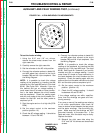
ROTOR RESISTANCE TEST (continued)
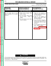
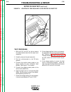
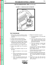
FIGURE F.2 – LEADS 200A AND 219 REMOVED
TEST PROCEDURE
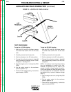
1. With the 5/16” and 3/8” nut drivers, remove
the sheet metal screws from the right hand
case side.
2. Carefully remove the right case side.
3. Conduct the test with the engine OFF.
4. Isolate the rotor electrically by removing
the generator brush leads. Refer to Figure
F.2 as you perform the remaining steps.
5. Remove lead #219 from the negative brush.
6. Remove lead #200A from the positive
brush.
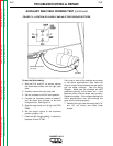
7. Measure the resistance across the rotor
slip rings.
a. Set the ohmmeter on the low scale
(X1).
b. Place one meter probe on one of the
rotor slip rings. Place the other probe
on the other slip ring.
c. Check the resistance across the slip
rings. It should read approximately 5
or 6 ohms.
8. Measure the resistance to ground.
A. Set the ohmmeter on the high scale
(X100,000).
B. Place one probe on either of the slip
rings. Place the other probe on any
good unpainted ground. The machine
ground stud works well.
C. Check the resistance. It should read
very high, at least 0.5 megohm
(500,000 ohms).
If the test does not meet the resistance
specifications, then the rotor may be
faulty. Replace the rotor.
If the test does meet the resistance speci-
fications, then the rotor is okay.
9. Connect lead #200A to the positive brush,
which is the one nearest the rotor lamina-
tion. Connect lead #219 to the negative
brush.
10. Reinstall the right case side using the
sheet metal screws and the 5/16” and
3/8” nut drivers.