


Return to Section TOC Return to Section TOC Return to Section TOC Return to Section TOC
Return to Master TOC Return to Master TOC Return to Master TOC Return to Master TOC
TROUBLESHOOTING & REPAIR
F-9 F-9
RANGER 10-LX
TROUBLESHOOTING GUIDE Observe Safety Guidelines
detailed in the beginning of this manual.
CAUTION
If for any reason you do not understand the test procedures or are unable to perform the test/repairs safely, con-
tact the Lincoln Electric Service Department for electrical troubleshooting assistance before you proceed. Call
216-383-2531 or 1-800-833-9353.
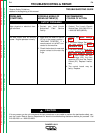
PROBLEMS
(SYMPTOMS)
POSSIBLE AREAS OF
MISADJUSTMENT(S)
RECOMMENDED
COURSE OF ACTION
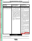
OUTPUT PROBLEMS
No constant voltage (CV) welding
output. Constant current (CC) and
the auxiliary power are operating
normally.
1. Make sure the Range switch
(S2) is in the proper position
and “seated” correctly.
2. Put the control cable switch
(S8) in the “No control cable”
position. If CV output is
restored, the output contactor
is functioning correctly. Place a
jumper wire from pin “D” to Pin
“C” in the 14 pin amphenol. If
CV output is restored, the prob-
lem is in the control cable or
wire feeder. If CV output is NOT
restored, check the continuity
of leads #2 and #4 within the
wiring harness. See Wiring
Diagram.
3. Make sure the wire feeder and
welding cables are connected
correctly.
1. Check the operation of the CV
output contactor. Make certain
it is “closing” and the contacts
have continuity when contactor
is activated. See Wiring
Diagram.
2. Check the operation of the
Range swtich (S2), and check
the associated wires for loose
or faulty connections. See
Wiring Diagram.
3. Check the continuity from leads
C1, C2, C3, and C4 to lead W1
located in the main stator. See
Wiring Diagram.
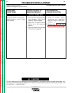
The constant voltage (CV) welding
output is low or unstable.
Constant current (CC) and auxiliary
power are operating normally.
1. Make sure the Range switch
(S2) is in the proper position
(CV) and “seated” correctly.
2. Make sure the wire feeder and
welding cables are connected
correctly.
1. Check the operation of the CV
output contactor. Make sure it
is “closing” and the contacts
have continuity when the con-
tactor is activated. See Wiring
Diagram.
2. Check the operation of the
Range switch (S2), and check
the associated wires for loose
or faulty connections. See
Wiring Diagram.
3. The capacitor bank (C6, C7, C8,
and C9) may be faulty. Check
or replace.