


Return to Section TOC Return to Section TOC Return to Section TOC Return to Section TOC
Return to Master TOC Return to Master TOC Return to Master TOC Return to Master TOC
TROUBLESHOOTING & REPAIR
F-58 F-58
RANGER 10-LX
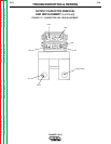
OUTPUT RECTIFIER BRIDGE REMOVAL
AND REPLACEMENT (continued)
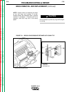
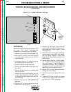
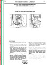
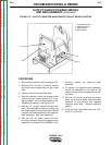
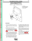
FIGURE F.14 - OUTPUT RECTIFIER CONNECTIONS
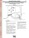
PROCEDURE
1. Perform this procedure with the engine OFF.
2. With the 5/16” and 3/8” nut drivers, remove
the sheet metal screws from the left and right
case sides.
3. Carefully remove the left and right case
sides. Note that the output rectifier is di-
vided into two parts. The positive portion is
located on the lower right side and the neg-
ative portion on the lower left side of the
machine.
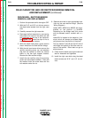
For the remaining steps refer to FIgure F.14.
4. With the 1/2” wrench, remove the diode pig-
tails and heavy leads from the terminal studs.
Note lead and washer placement: nut, split
washer, flat washer, leads. Label leads for
reassembly. See wiring diagram.
5. With the 1/2” wrench, remove the two heavy
leads and one small lead from the rectifier
heat sink plate. (Note that the small lead is
always on top for reassembly.)
6. With the 7/16” wrench, remove the nut and
washers holding the top stud assembly to the
rectifier mounting bolts.
7. With the 7/16” wrench, remove the nuts, lock
washers, and flat washers from the two top
mounting bolts. (Note insulator place-
ment.)
8. With the 3/8” nut driver, remove the two bot-
tom mounting sheet metal screws. (Note
insulator placement - upon reassembly the
heat sink must be electrically insulated from
the frame of the Ranger 10-LX.)
Left Side (–) Right Side (+)