


Return to Section TOC Return to Section TOC Return to Section TOC Return to Section TOC
Return to Master TOC Return to Master TOC Return to Master TOC Return to Master TOC
TROUBLESHOOTING & REPAIR
F-38 F-38
RANGER 10-LX
ENGINE THROTTLE ADJUSTMENT TEST (continued)
Oscilloscope Method:
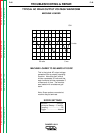
1. Connect the oscilloscope to the 115 VAC
receptacle, according to the manufactur-
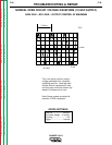
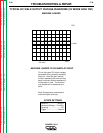
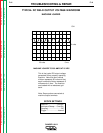
er’s instructions. At 3700 RPM, the wave-
form should exhibit a period of 15.8 mil-
liseconds. At 2200 RPM, the waveform
should exhibit a period of 27.02 millisec-
onds. Refer to NORMAL OPEN CIRCUIT
VOLTAGE WAVEFORM (115 VAC SUPPLY)
HIGH IDLE – NO LOAD in this section of
the manual.
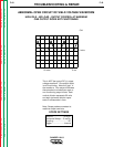
2. If either waveform periods is incorrect,
adjust the throttle as follows:
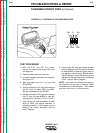
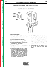
Adjust HIGH IDLE: First make sure there is
NOT a load on the machine. Use the
10mm wrench to loosen the lock nut. See
Figure F.9 for location of the adjustment
screw and lock nut. With the 10mm
wrench, turn the adjustment screw coun-
terclockwise to increase the high idle RPM.
Note: It is usually NOT necessary to cut or
remove the wire and seal. Adjust the
speed until the period is 15.8 milliseconds.
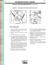
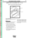
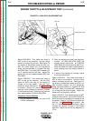
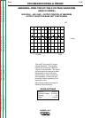
Adjust LOW IDLE: First make sure there is
NOT a load on the machine. Set the IDLE
switch to AUTO and wait for the engine to
change to low idle speed. Use the 7/16”
wrench to loosen the lock nut. See Figure
F.10 for location. Use the 1/2” wrench to
adjust the solenoid, which changes the
amount of throw in the throttle lever arm.
Adjust the nut until the period is 27.02 mil-
liseconds.
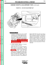
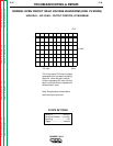
FIGURE F.10 – LOW IDLE ADJUSTMENT NUT
7/16” Lock Nut
1/2” Adjustment Nut