


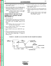

7. Place the WIRE FEEDER switch in the “WITH CON-
TROL CABLE” position.
8. Adjust wire feed speed at the wire feeder and set
the welding voltage with the output “CONTROL” to
a CV (constant voltage) position at the welder.
NOTE: If optional remote control is used, place
the output control switch in the “CON-
TROL REMOTE” position.
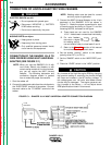
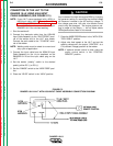
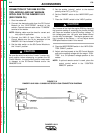
CONNECTION OF THE LN-25 TO THE
RANGER 10-LX “ACROSS THE ARC”
(SEE FIGURE C.2.)
1. Shut the welder off.
2. Connect the electrode cable from the LN-25 to the
“ELECTRODE” terminal of the welder. Connect the
work cable to the “TO WORK” terminal of the
welder.
NOTE: Welding cable must be sized for current
and duty cycle of application.
3. Set the welder “polarity” switch to the desired
polarity, either DC (-) or DC (+).
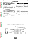
4. Set the “RANGE” switch to the “WIRE FEED” posi-
tion.
5. Attach the single lead from the LN-25 control box
to the work using the spring clip on the end of the
lead. This is only a control lead — it carries no
welding current.
6. Place the “IDLER” switch in the “AUTO” position.
7. Place the WIRE FEEDER switch in the “NO CON-
TROL CABLE” position.
8. Adjust wire feed speed at the LN-25 and adjust the
welding voltage with the output “CONTROL” at the
welder.
NOTE: If optional remote control is used, place
the output control switch in the “CON-
TROL REMOTE” position.
ACCESSORIES
C-5 C-5
RANGER 10-LX
Return to Section TOC Return to Section TOC Return to Section TOC Return to Section TOC
Return to Master TOC Return to Master TOC Return to Master TOC Return to Master TOC
FIGURE C.2 – RANGER 10-LX/LN-25 ACROSS THE ARC CONNECTION DIAGRAM
K857