


TROUBLESHOOTING & REPAIR
F-36 F-36
RANGER 10-LX
Return to Section TOC Return to Section TOC Return to Section TOC Return to Section TOC
Return to Master TOC Return to Master TOC Return to Master TOC Return to Master TOC
ENGINE THROTTLE ADJUSTMENT TEST (continued)
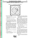
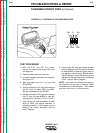
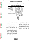
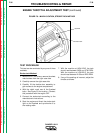
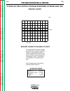
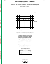
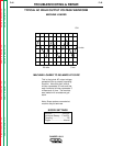
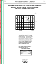
FIGURE F.8 – MARK LOCATION, STROBE/TACH METHOD
TEST PROCEDURE
This test can be conducted by any one of three
methods.
Strobe-tach Method:
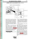
1. With the 5/16” nut drivers, remove the sheet
metal screws from the right case side.
2. Carefully remove the right case side.
3. Carefully lift the double door assembly to
gain access to the engine compartment.
4. With the chalk, mark one of the flywheel
bolts. See Figure F.8 for location. Conduct
this procedure with the engine OFF.
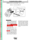
5. Connect the strobe-tach according to the
manufacturer’s instructions.
6. Start the engine and direct the strobe-tach
light on the flywheel and synchronize it to
the rotating mark.
7. With the machine at HIGH IDLE, the tach
should read between 3650 and 3700 RPM.
WIth the machine at LOW IDLE, the tach
should read between 2150 and 2220 RPM.
8. If any of the readings is incorrect, adjust the
throttle as follows.
Flywheel
Chalk mark