


Return to Section TOC Return to Section TOC Return to Section TOC Return to Section TOC
Return to Master TOC Return to Master TOC Return to Master TOC Return to Master TOC
TROUBLESHOOTING & REPAIR
F-68 F-68
RANGER 10-LX
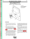
23. Using the 5/16” wrench, remove the three
sheet metal screws holding the front vertical
baffle to the base of the machine.
24. Clear all stator leads and cut any necessary
cable ties.
25. Carefully lift and pivot the front panel
assembly, along with the reactor, around to
the right side of the machine. Support the
unit with a box or large pan. See Figure
F.19.
26. Remove the two 3/8” nuts and bolts that
hold the stator mounting bracket to the
base of the machine. See Figure F.18.
27. Remove the 1/2” blower (fan) bolt the blow-
er, and the two 3/8” screws that hold the
rotor bearing in place. You will need to use
a gear puller to remove the blower.
28. Support the engine. See Figure F.18.
29. Remove the eight 9/16” bolts that mount
the stator to the engine.
30. Using a gear puller, carefully remove the
stator.
ROTOR REMOVAL PROCEDURE
1. Support the rotor. See Figure F.18.
2. Remove the six 1/2” rotor bolts and spacers.
Caution: The rotor will be free to fall when the
bolts are removed.
3. Rotor bearing must be removed before sta-
tor is reinstalled. (Install bearing after stator
is reinstalled).
4. Install bearing tolerance ring.
5. Carefully install stator and check air gap
.015” (minimum).
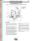
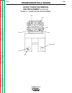
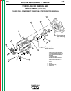
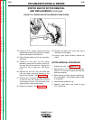
FIGURE F.19- ENGINE AND ROTOR REMOVED FROM STATOR
STATOR AND/OR ROTOR REMOVAL
AND REPLACEMENT (continued)