


Return to Section TOC Return to Section TOC Return to Section TOC Return to Section TOC
Return to Master TOC Return to Master TOC Return to Master TOC Return to Master TOC
TROUBLESHOOTING & REPAIR
F-63 F-63
RANGER 10-LX
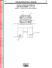
OUTPUT CAPACITOR REMOVAL
AND REPLACEMENT (continued)
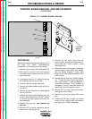
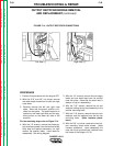
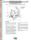
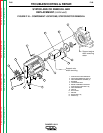
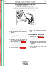
FIGURE F.16 – OUTPUT CONTACTOR LOCATION
PROCEDURE
1. Perform this procedure with the engine OFF.
2. With the 5/16” and 3/8” nut drivers, remove
the sheet metal screws from the left case
side.
3. Carefully remove the left case side.
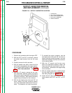
4. With the needle nose pliers, remove the five
small leads connected to the output contac-
tor coil (leads #224F, #224K, #14B, #2C and
#2D). Note lead placement. See Figure
F.17.
5. With the 1/2” wrench, remove the nut, bolt,
and associated washers holding the heavy
lead and two small leads (#241 and #241A) to
the output contactor. Also remove the heavy
copper strap connected to the contactor.
6. With the slot head screw driver and 3/8” nut
driver, remove the three mounting screws,
nuts, and associated washers from the con-
tactor. The contactor can now be removed.
7. To reinstall the output contactor, use the
slot head screw driver and 3/8” nut driver to
attach the three mounting screws, nuts and
associated washers that hold the contactor
to the vertical baffle.
8. WIth the 1/2” wrench and the two nuts,
bolts and associated washers, attach the
heavy lead and two small leads to the out-
put contactor. Also attach the copper strap
to the contactor.
9. With the needle nose pliers, carefully attach
the five small leads to the contactor coil.
See Wiring Diagram and Figure F.17.
10. Install the left case side using the sheet
metal screws and 5/16” and 3/8” nut dri-
vers.
1. CONTACTOR
2. COIL LEAD CONNECTIONS
3. HEAVY LEAD CONNECTIONS
4. MOUNTING HARDWARE
5. VERTICAL BAFFLE
4
4
3
2
1
5