


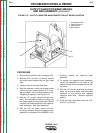

REASSEMBLY NOTES
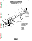
1. Be sure to remove the rotor bearing from
the stator frame before reinstalling the
rotor/stator Also remove the tolerance
ring.
2. Install the rotor to the flex plate and install
the flex plate to the engine.
3. Carefully install the stator. Tighten the
eight bolts finger-tight only.
4. Install a new tolerance ring and press in a
new rotor bearing.
5. Tighten stator bolts.
6. Check the air gap for .015” (minimum).
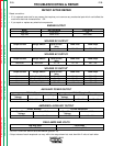
LEAD RECONNECTION
CHECKLIST
Engine
Lead #226 to fuel gauge
Front Panel/PC Board
4 stator leads to Range switch
Lead #31 from CB2
Leads #42 and #32 between stator and 14-
pin amphenol
Lead #3 to 115 VAC receptacle
Lead #5 to 115 VAC receptacle
Lead #5D to common ground screw
Lead #6 to 115/230 VAC receptacle
Leads #7 and #9 to field bridge rectifier
Lead W1 (heavy lead) to left side output
rectifier assembly
Lead S2 (heavy lead) to left side output rec-
tifier assembly
Lead W2 to S1
TROUBLESHOOTING & REPAIR
F-69 F-69
RANGER 10-LX
Return to Section TOC Return to Section TOC Return to Section TOC Return to Section TOC
Return to Master TOC Return to Master TOC Return to Master TOC Return to Master TOC
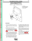
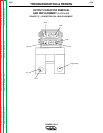
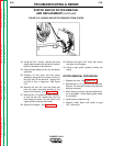
STATOR AND/OR ROTOR REMOVAL
AND REPLACEMENT (continued)