


Return to Master TOC Return to Master TOC Return to Master TOC Return to Master TOC
Section F-1 Section F-1
RANGER 10-LX
Troubleshooting & Repair Section.................................................................................Section F
How to Use Troubleshooting Guide ......................................................................................F-2
PC Board Troubleshooting Procedures.................................................................................F-3
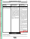
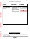
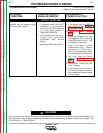
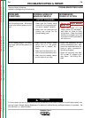
Troubleshooting Guide.................................................................................................F4 - F-20
Test Procedures
Rotor Voltage Test.........................................................................................................F-21
Rotor Resistance Test ...................................................................................................F-23
Auxiliary and Field Winding Test ...................................................................................F-25
Output Rectifier Bridge Test..........................................................................................F-29
Charging Circuit Test.....................................................................................................F-31
Protection Relay (CR1) Test ..........................................................................................F-33
Engine Throttle Adjustment Test ...................................................................................F-35
Oscilloscope Waveforms .....................................................................................................F-39
Normal Open Circuit Voltage Waveform (115 VAC Supply)..........................................F-39
Typical DC Weld Output Waveform (CV Mode) – Machine Loaded..............................F-40
Typical DC Weld Output Waveform – Machine Loaded................................................F-41
Typical AC Weld Output Waveform – Machine Loaded................................................F-42
Abnormal Open Circuit Weld Voltage Waveform (one diode open)..............................F-43
Abnormal Open Circuit DC Weld Voltage Waveform
(High CV Mode) – Output Capacitor Bank not Functioning ...................................F-44
Normal Open Circuit Weld Voltage Waveform (High CV Mode) ...................................F-45
Normal Open Circuit DC Weld Voltage Waveform........................................................F-46
Normal Open Circuit AC Weld Voltage Waveform ........................................................F-47
Replacement Procedures ....................................................................................................F-48
Brush Removal and Replacement ................................................................................F-48
Field Capacitor and Rectifier Bridge Removal and Replacement ................................F-51
Control Board Removal and Replacement ...................................................................F-54
Output Rectifier Bridge Removal and Replacement.....................................................F-57
Output Capacitor Removal and Replacement..............................................................F-60
Output Contactor Removal and Replacement..............................................................F-62
Stator and/or Rotor Removal and Replacement (Kit S20788)......................................F-65
Retest After Repair ..............................................................................................................F-70
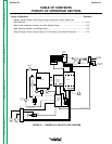
TABLE OF CONTENTS
TROUBLESHOOTING & REPAIR SECTION