


Return to Section TOC Return to Section TOC Return to Section TOC Return to Section TOC
Return to Master TOC Return to Master TOC Return to Master TOC Return to Master TOC
TROUBLESHOOTING & REPAIR
F-59 F-59
RANGER 10-LX
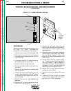
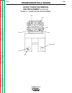
OUTPUT RECTIFIER BRIDGE REMOVAL
AND REPLACEMENT (continued)
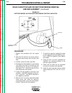
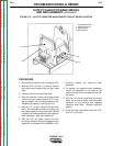
9. Clear the leads and carefully remove the
heat sink assembly.
10. Repeat the above procedure to remove
the other half of the output rectifier.
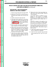
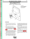
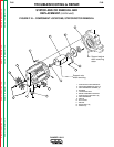
REASSEMBLY:
When reassembling, use Dow Corning 340 on
all aluminum electrical connection surfaces.
1. With the 3/8” nut driver, mount the heat sink
assemblies at the bottom using the sheet
metal mounting screws. Be sure to place
the insulators properly so that the heat
sinks are electrically insulated from the
machine frame.
2. With the 1/2” wrench, reattach the two
heavy leads and one small lead to the heat
sink plate. (Small lead goes on top.)
3. With the 7/16” wrench, fit the flat washers,
lock washers, and nuts to the two top
mounting bolts.
4. With the 7/16” wrench, fit the washers and
nut to hold the top stud assembly to the
rectifier mounting bolts.
5. WIth the 1/2” wrench, reattach the diode
pigtails and heavy leads to the terminal
studs. Placement is: leads, flat washer, split
washer, nut.
6. With the 5/16” and 3/8” nut drivers, replace
the machine case sides and top.