


Return to Section TOC Return to Section TOC Return to Section TOC Return to Section TOC
Return to Master TOC Return to Master TOC Return to Master TOC Return to Master TOC
TROUBLESHOOTING & REPAIR
F-53 F-53
RANGER 10-LX
FIELD CAPACITOR AND/OR RECTIFIER BRIDGE REMOVAL
AND REPLACEMENT (continued)
PROCEDURE - RECTIFIER BRIDGE
REMOVAL AND REPLACEMENT
1. Perform this procedure with the engine OFF.
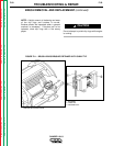
2. WIth the 5/16” and 3/8” nut drivers, remove
the sheet metal screws from the right case
side.
3. Carefully remove the right case side.
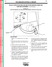
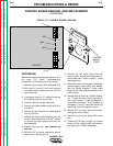
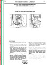
4. Discharge the field capacitor by connecting
the jumper wire clips on the white and red
wire terminals on the top of the capacitor.
See Figure F.12. Leave the clips on for at
least 5 seconds, then remove.
5. With the needle nose pliers, gently remove
the six wires from the field rectifier bridge.
6. WIth the slot head screw driver remove the
rectifier mounting screw, nut, and washers
that hold the rectifier to either the vertical
baffle or the fuel tank support bracket.
Remove the field rectifier bridge.
7. Install the new rectifier using the mounting
screw and associated hardware. Place the
flat washer under the screw head and the
lock washer under the nut.
8. Replace the wires to their appropriate loca-
tions on the new rectifier bridge. (See the
Wiring Diagram.)
Leads #200, #200A and #200B are piggy-
backed on the positive (+) terminal.
Depending on the bridge used, this corner
may be beveled and/or marked with a +
sign.
Lead #201 is located on the negative (-) ter-
minal, which will always be located diago-
nally across from the positive (+) terminal.
The two leads #7 and #9 are the AC side of
the bridge and attach to the other two cor-
ners of the rectifier. Either lead can go on
either terminal.
9. Check that the leads are not grounded and
also for clearance and tightness.
10. Install the right case side using the sheet
metal screws and 5/16” and 1/8” nut dri-
vers.