


TROUBLESHOOTING & REPAIR
F-34 F-34
RANGER 10-LX
Return to Section TOC Return to Section TOC Return to Section TOC Return to Section TOC
Return to Master TOC Return to Master TOC Return to Master TOC Return to Master TOC
PROTECTION RELAY (CR1) TEST (continued)
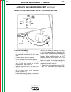
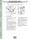
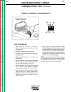
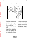
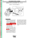
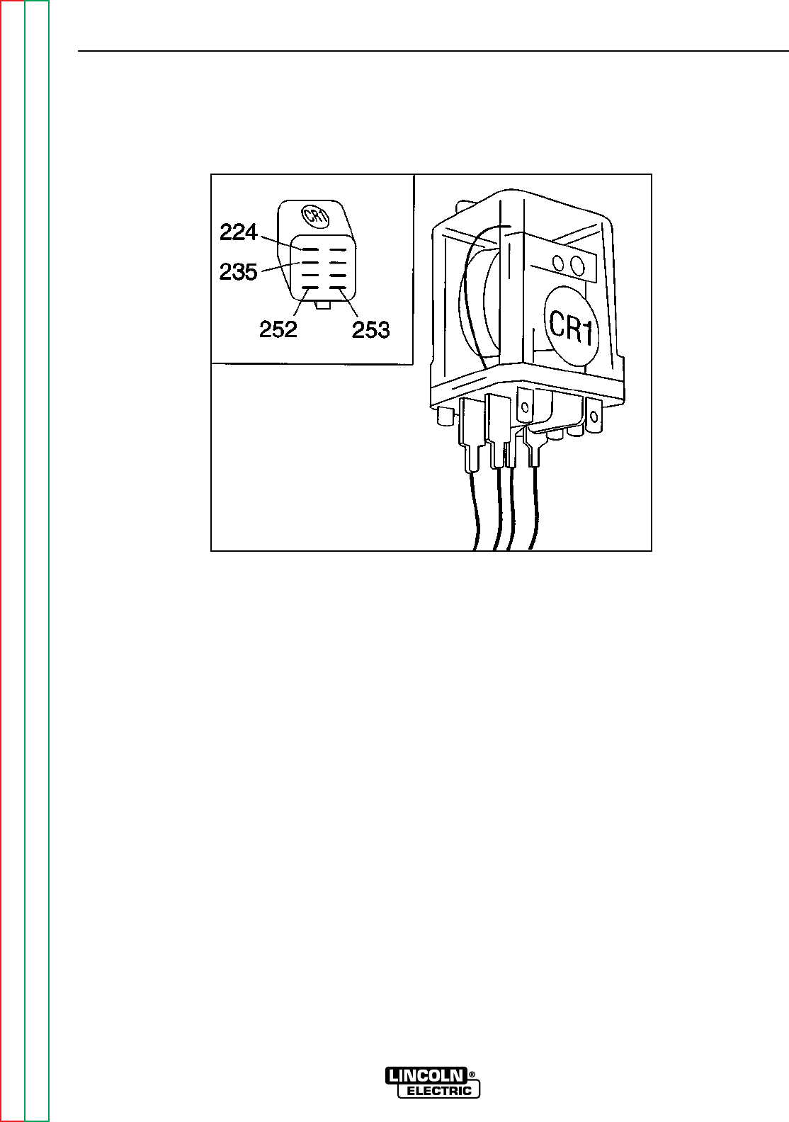
FIGURE F.7 – CR1 LEAD CONNECTIONS
TEST PROCEDURE
1. Using the 5/16” and 3/8” nut drivers,
remove the sheet metal screws from the
left case side.
2. Carefully remove the left case side.
3. Conduct this test with the engine OFF.
4. Remove leads #252, #253, #224 and #235
from relay CR1. See Figure F.7.
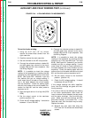
5. Using the 12VDC power supply, apply
12VDC to the coil terminals “A” and “B” of
the relay.
6. Check visually to see if the relay is operat-
ing when voltage is applied to the coil ter-
minals. If the relay IS operating, proceed
to step #7. If the relay is NOT operating
when coil voltage is applied, then check
the resistance of the coil. Normal coil
resistance is 100 to 150 ohms. If the relay
coil is “shorted” or “open,” the relay will
NOT operate. Replace the relay.
7. With 12VDC applied to the relay coil, use
the ohmmeter to check for continuity (zero
ohms) from terminals #4 to #7. If zero or a
very low resistance is measured, the con-
tacts are okay. If a high or infinite resis-
tance is measured, the contacts are faulty.
If NO voltage is applied to the coil termi-
nals, the resistance from #4 to #7 should
be infinite.
8. Install the left case side using the 5/16”
and 3/8” nut drivers and sheet metal
screws.