


Return to Section TOC Return to Section TOC Return to Section TOC Return to Section TOC
Return to Master TOC Return to Master TOC Return to Master TOC Return to Master TOC
TROUBLESHOOTING & REPAIR
F-56 F-56
RANGER 10-LX
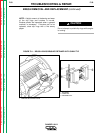
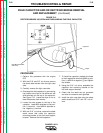
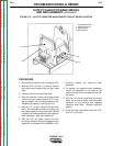
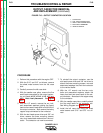
16. Connect current sensing leads #254 and
#254A. See the Wiring Diagram for the
proper connections.
17. Connect the two molex plugs.
18. Connect the three individual leads #213,
#222 and #5C.
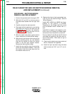
19. Replace any cable ties that were cut dur-
ing the removal procedure.
20. With the 5/16” nut driver, install the control
board cover.
21. Install the right case side, top, gaskets and
double door support rod.
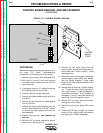
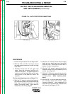
CONTROL BOARD REMOVAL
AND REPLACEMENT (continued)