


ACCESSORIES
C-6 C-6
RANGER 10-LX
Return to Section TOC Return to Section TOC Return to Section TOC Return to Section TOC
Return to Master TOC Return to Master TOC Return to Master TOC Return to Master TOC
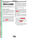
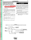
CONNECTION OF THE LN-7 TO THE
RANGER 10-LX USING K584 INPUT
CABLE ASSEMBLY (SEE FIGURE C.3.)
NOTE: If your LN-7 comes equipped with a K291 or
K404 Input cable, refer to Connection of the
LN-7 Using K867 Universal Adapter, rather
than this discussion, to connect your
RANGER 10-LX for wire feed welding.
1. Shut the welder off.
2. Connect the electrode cable from the K584-XX
Input Cable Assembly to the “ELECTRODE” termi-
nal of the welder and to the LN-7 wire feeder.
Connect the work cable to the “TO WORK” termi-
nal of the welder.
NOTE: Welding cable must be sized for current and
duty cycle of application.
3. Connect the input cable from the K584-XX Input
Cable Assembly to the 14 pin amphenol on the
RANGER 10-LX and the input cable plug on the
LN-7.
4. Set the welder “polarity” switch to the desired
polarity, either DC (-) or DC (+).
5. Set the “RANGE” switch to the “WIRE FEED” posi-
tion.
6. Place the “IDLER” switch in the “HIGH” position.
Any increase of the high idle engine RPM by changing
the governor setting or overriding the throttle linkage
will cause an increase in the AC auxiliary voltage. If
this voltage goes over 140 volts, wire feeder control
circuits may be damaged. The engine governor set-
ting is preset at the factory — do not adjust above
RPM specifications listed in this manual.
7. Place the WIRE FEEDER switch in the “WITH CON-
TROL CABLE” position.
8. Adjust wire feed speed at the LN-7 and set the
welding voltage with the output “CONTROL” at a
CV (constant voltage) position at the welder.
NOTE: If optional remote control is used, place the
output control switch in the “CONTROL
REMOTE” position.
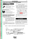
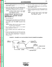
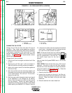
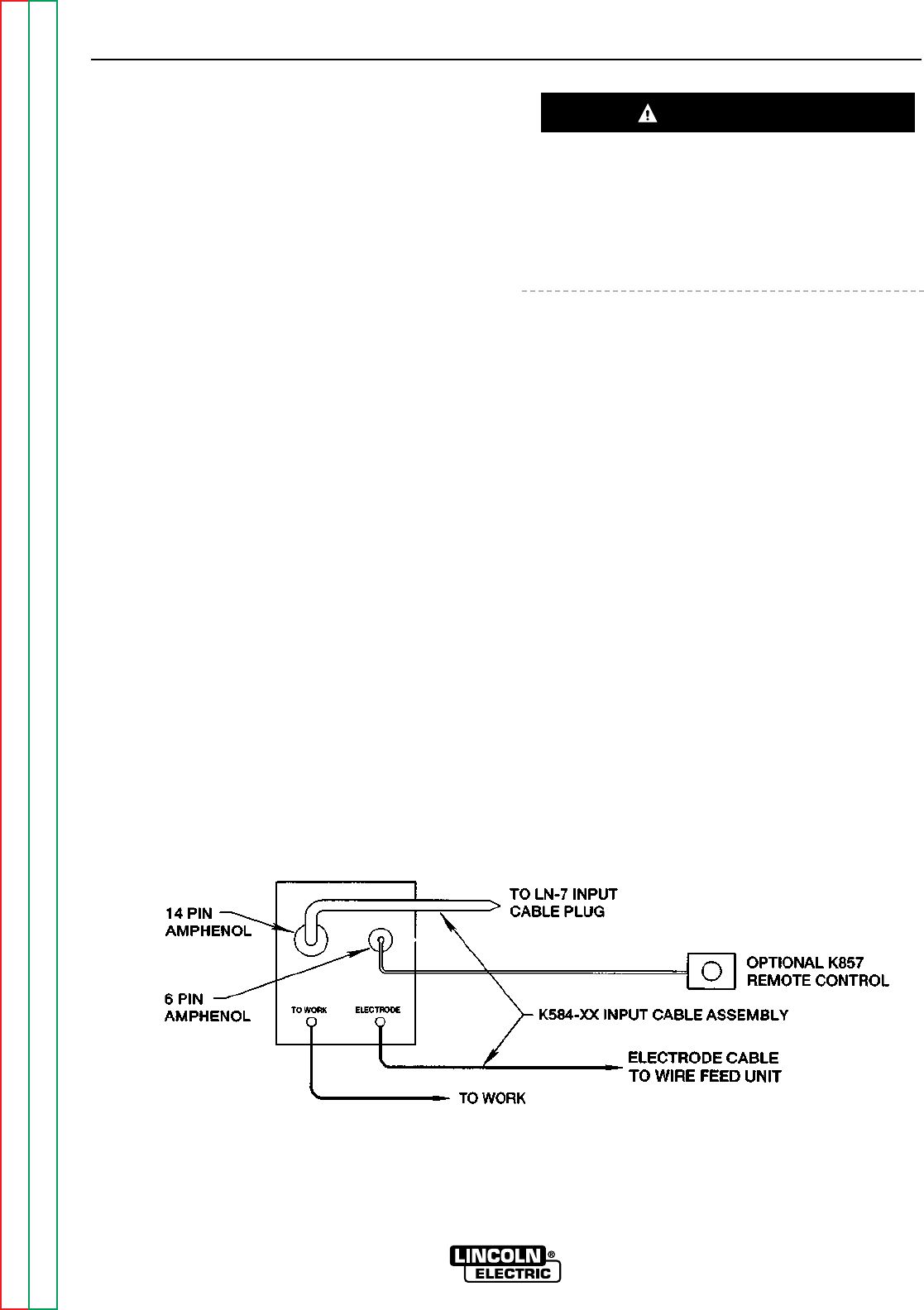
FIGURE C.3
RANGER 10-LX/LN-7 WITH K584 INPUT CABLE ASSEMBLY CONNECTION DIAGRAM
CAUTION