


Return to Section TOC Return to Section TOC Return to Section TOC Return to Section TOC
Return to Master TOC Return to Master TOC Return to Master TOC Return to Master TOC
TROUBLESHOOTING & REPAIR
F-28 F-28
RANGER 10-LX
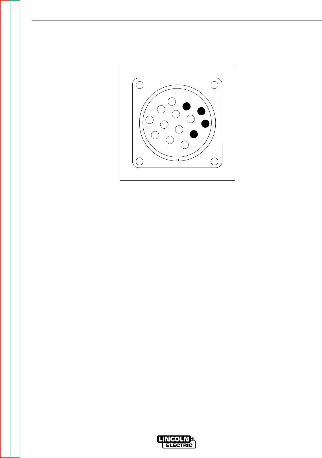
AUXILIARY AND FIELD WINDING TEST (continued)
Z
W
Y
X
K
B
I
H
N
L
C
D
M
G
E
F
J
A
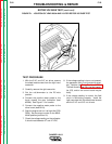
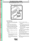
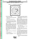
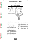
FIGURE F.4A – 14 PIN AMPHENOL PIN ASSIGNMENTS
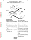
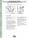
To test the feeder winding:
1. Using the 5/16” and 1/8” nut drivers,
remove the sheet metal screws from the
right case side.
2. Carefully remove the right case side.
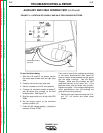
3. Set the voltmeter to the AC volts position.
4. Connect the voltmeter probes to leads #31
and #32 where they connect to the circuit
breaker CB2 and the 14 pin amphenol. See
the Wiring Diagram.
NOTE: It is possible to check this voltage
reading at the amphenol by inserting the test
probes at pin A (for lead #32) and pin J (for lead
#31A). See Figure F.4A. However, if you use
this method and get no voltage reading, it
could mean there is a break or loose connec-
tion in the leads between the circuit breaker
and the amphenol. Check the reading again
and with one probe at the circuit breaker con-
nection for lead #31 and the other probe at
amphenol pin A.
5. Start the engine and run it at high idle (3700
RPM).
6. Set the output control to the maximum
position (position 10).
8. Check the AC voltage reading. It should be
between 115 and 126 VAC.
9. Connect the voltmeter probes to leads #31
and #42 where they connect to the circuit
breaker CB2 and the 14 pin amphenol. See
the Wiring Diagram.
NOTE: It is possible to check this voltage
reading at the amphenol by inserting the test
probes at pin K (for lead #42) and I (for lead
#31B). See Figure 4A. However, if you use this
method and get no voltage reading, it could
mean there is a break or loose connection in
the leads between the circuit breaker and the
amphenol. Check the reading again with one
probe at the circuit breaker connection for lead
#31 and the other probe at amphenol pin K.
10. Set the output control to the maximum
position. (position 10).
11. Check the AC voltage reading. It should
be between 43 and 50 VAC.
If the voltage readings are within specifica-
tions, then the windings are good and func-
tioning correctly.
If any one or more of the readings are missing
or not within specifications, then check for
loose or broken wires between the test points
and the stator windings. See the wiring dia-
gram. Make sure that the windings are NOT
grounded internally to the stator iron. If the
leads are intact, then the stator may be faulty.
Replace the stator.
12. Reinstall the right case side using the
5/16” and 3/8” nut drivers and sheet metal
screws.