


Return to Section TOC Return to Section TOC Return to Section TOC Return to Section TOC
Return to Master TOC Return to Master TOC Return to Master TOC Return to Master TOC
TROUBLESHOOTING & REPAIR
F-55 F-55
RANGER 10-LX
CONTROL BOARD REMOVAL AND REPLACEMENT
(continued)
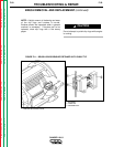
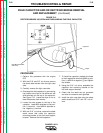
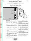
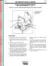
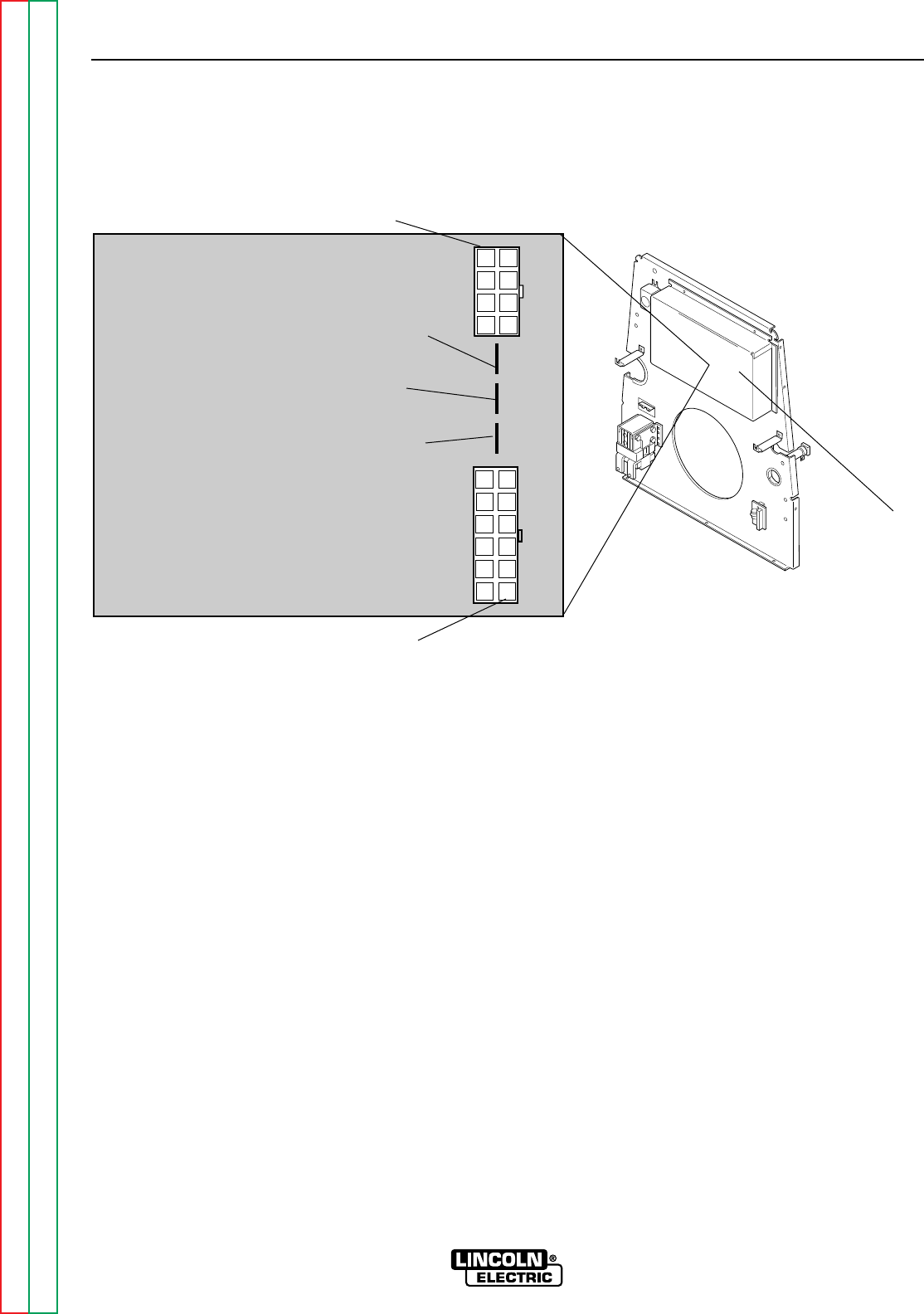
FIGURE F.13 - CONTROL BOARD LOCATION
PROCEDURE
Before starting the following procedure, refer to
the topic “PC Board Troubleshooting
Procedures” at the beginning of this section.
1. Perform this procedure with the engine OFF.
2. With the 5/16” and 3/8” nut drivers, remove
the sheet metal screws from the top and
right case side.
3. If necessary, use the 1/2” wrench to remove
the exhaust pipe from the muffler.
4. Carefully remove the right case side.
5. Remove the rubber gasket (cover seal) from
the lift bail.
6. Remove the fuel cap and the rubber gasket
from the fill tube.
7. Unlatch the double door assembly and use
the slot head screwdriver and 3/8” wrench
to remove the door support rod from the
door assembly.
8. Remove the case top, then reinstall the
fuel cap.
9. With the 5/16” nut driver, remove the control
board cover. See Figure F.13.
10. Remove the two molex plugs from the
control board. Also remove the three indi-
vidual leads #213, #222 and #5C. (Note
lead placement.)
11. Detach the two in-line connectors from the
current sensing leads (#254 and #254A).
See the Wiring Diagram. These leads
attach to the current sensor located on the
control board.
12. Remove lead #3 from the 115VAC recepta-
cle. Thread the lead through the hole in
the current sensor in order to separate it
from the control board. It will probably be
necessary to cut any cable ties restraining
the wiring. Use the diagonal cutters.
13. With the 1/4” nut driver, remove the screws
holding the control board.
14. Replace the old control board with a new
one.
15. Thread lead #3 back through the current
sensor on the control board and reattach
the lead to the 115VAC receptacle.
CONTROL
J1
J2
#5C
#222
#213
CONTROL
BOARD
COVER