


Return to Section TOC Return to Section TOC Return to Section TOC Return to Section TOC
Return to Master TOC Return to Master TOC Return to Master TOC Return to Master TOC
INSTALLATION
IDEALARC DC-1000
A-4
FUSE AND WIRE SIZES
Protect the input circuit with the super lag fuses or
delay type circuit breakers listed on the
Technical
Specifications
page of this manual for the machine
being used. They are also called inverse time or ther-
mal/magnetic circuit breakers.
DO NOT use fuses or circuit breakers with a lower
amp rating than recommended. This can result in nui-
sance tripping caused by inrush current even when
machine is not being used for welding at high output
currents.
Use input and grounding wire sizes that meet local
electrical codes, or see the
Technical Specifications
page in this manual.
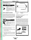
GROUND CONNECTION
Ground the frame of the machine. A ground terminal
marked with the symbol is located inside the Case
Back of the machine. Access to the rear input panel is
at the upper rear of the machine. See your local and
national electrical codes for proper grounding meth-
ods.
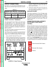
INPUT POWER SUPPLY CONNECTIONS
A qualified electrician should connect the input power
supply leads.
1. Follow all national and local electrical codes.
2. Follow Input Supply Connection Diagram located
on the inside of the machine.
3. Use a three-phase line.
4. Remove Input Access Door at upper rear of
machine.
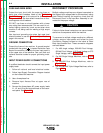
5. Connect the three-phase AC power supply leads
L1, L2, and L3 to the input terminals on the recon-
nect panel. See Figure A.2
RECONNECT PROCEDURE
Multiple voltage machines are shipped connected to
the highest input voltage listed on the machine’s rating
plate. Before installing the machine, check that the
Reconnect Panel in the Input Box Assembly is con-
nected for the proper voltage.
Failure to follow these instructions can cause immedi-
ate failure of components within the machine.
____________________________________________________
To reconnect a multiple voltage machine to a different
voltage, remove input power and follow the Input
Connection Diagram located on the inside of Case
Back Input Access Door. These connection diagrams
are listed below:
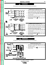
1. For 460 single voltage, 230/460 Dual Voltage,
220/440 Dual Voltage, 415 Single Voltage or 575
Single Voltage, refer to Figure A.3a.
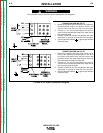
2. For 380 Single Voltage Machines, refer to Figure
A.3b.
3. For 380/500 Dual Voltage Machines, refer to
Figure A.3c.
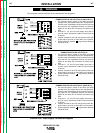
4. For 220/380/440 Triple Voltage Machines, refer to
Figure A.3d
CAUTION
A-4