


Return to Section TOC Return to Section TOC Return to Section TOC Return to Section TOC
Return to Master TOC Return to Master TOC Return to Master TOC Return to Master TOC
F-24
TROUBLESHOOTING & REPAIR
F-24
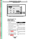
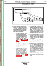
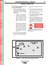
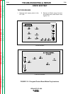
FIRING BOARD TEST
IDEALARC DC-1000
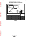
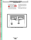
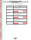
TABLE F.1 - LED 7, 8 and 9 Check List
IF
LED 7 is ON
LED 7 is OFF or is DIM-
MER than other LEDs
LED 8 is ON
LED 8 is OFF or is DIM-
MER than other LEDs
LED 9 is ON
LED 9 is OFF or is DIM-
MER than other LEDs
THEN
AC power is being supplied to the Firing Board from
leads #203 and #204 connected to the phase angle wind-
ing in the Main Transformer.
The proper AC voltage may not be reaching Firing Board.
Check for loose or faulty connections.
Perform Main
Transformer Test.
AC power is being supplied to the Firing Board from
leads #205 and #206 connected to the phase angle wind-
ing in the Main Transformer.
The proper AC voltage may not be reaching Firing Board.
Check for loose or faulty connections.
Perform Main
Transformer Test
.
AC power is being supplied to the Firing Board from
leads #207 and #208 connected to the phase angle wind-
ing in the Main Transformer.
The proper AC voltage may not be reaching Firing Board.
Check for loose or faulty connections.
Perform Main
Transformer Test
.