


B-5
OPERATION
B-5
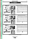
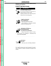
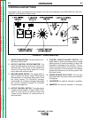
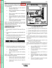
1. ON/OFF PUSH BUTTON: This push button turns
the machine ON or OFF
2. OUTPUT CONTROL POTENTIOMETER: This
control provides tapered, continuous control of the
machine output. The control can be rotated from
minimum to maximum while machine is under
load to adjust the machine output.
3. WELDING MODE SWITCH: This toggle switch is
used to select the proper welder performance
characteristics for the process being used. There
are three modes: CV (Constant Voltage)
Innershield®, CV (Constant Voltage) Submerged
Arc, and VV (Variable Voltage) CC (Constant
Current) Submerged Arc.
4. OUTPUT CONTROL SWITCH: This toggle switch
is used to switch between “Output Control at DC-
1000” for local control of machine output and
“Output Control Remote” for remote control of
machine output.
5. CONTROL CIRCUIT POLARITY SWITCH: This
toggle switch is used to set power source voltage
sensing polarity to match the polarity to which the
electrode is connected to the machine. This pro-
vides the correct polarity at the terminal strip for
correct operation of the automatic wire feeding
equipment powered by the auxiliary power from
the power source.
6. POWER SOURCE PILOT LIGHT: The red neon
light glows when the power source input contactor
is energized.
7. VOLTMETER: An optional voltmeter is available.
8. AMMETER: An optional ammeter is available.
IDEALARC - DC 1000
Return to Section TOC Return to Section TOC Return to Section TOC Return to Section TOC
Return to Master TOC Return to Master TOC Return to Master TOC Return to Master TOC
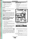
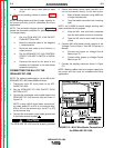
FIGURE B.1 - Control Panel Keys
CONTROLS AND SETTINGS
All operator controls and adjustments are located on the Case Front Assembly of the IDEALARC DC-1000. See
Figure B.1 for the location of each control.