


Return to Section TOC Return to Section TOC Return to Section TOC Return to Section TOC
Return to Master TOC Return to Master TOC Return to Master TOC Return to Master TOC
TROUBLESHOOTING & REPAIR
F-61
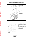
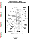
TRANSFORMER
REASSEMBLY
1. Using a hoist, carefully lift the top
iron onto the assembly. Lightly tap
on the top of the iron.
2. Position the transformer threaded
rods securing the transformer.
Using a 3/4” wrench, secure the six
nuts and lock washers. It may be
necessary to hold the threaded rods
to keep them from turning. Tighten
nuts to 39 - 41 Ft.-Lbs.
3. The primary coils should be ground
tested at 2700 VAC for one second.
The secondary coils should be
ground tested at 1500 VAC for one
second. The primary to secondary
insulation should be tested at 2700
VAC for one second.
4. Install the four brackets and two
bottom spacers in the position
noted at disassembly. Using a 1/2”
socket wrench, secure in position
with 16 screws (8 on each side)
onto the transformer side brackets.
5. With leads still attached, carefully
reposition the input contactor brack-
et onto the case back assembly.
Using a 3/8” socket wrench, secure
in position using two screws
removed previously.
6. Attach lead #220 onto the reed
switch (3CR).
7. Attach lead #256 onto the choke
thermostat.
8. Reconnect lead #211 and #212 to
the in-line connectors.
9. Attach lead #271 onto resistor R3.
10. Perform
Lift Bail Installation
Procedure
.
11. Replace any cable ties or restraints
which were cut to remove the top
transformer iron.
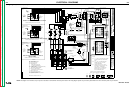
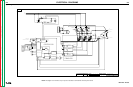
TRANSFORMER INSTALLATION
IDEALARC DC-1000
F-61