


Return to Section TOC Return to Section TOC Return to Section TOC Return to Section TOC
Return to Master TOC Return to Master TOC Return to Master TOC Return to Master TOC
TROUBLESHOOTING & REPAIR
F-51
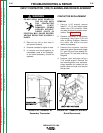
10. Cut any necessary cable ties to
allow for the SCR bridge assembly
removal.
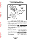
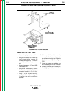
11. Using a 1/2” socket wrench, remove
the four screws (2 on each side)
holding the transformer side panels
and SCR assembly rails to the main
transformer. See Figure F.23.
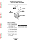
12. Remove leads #217 and #222 from
resistor R2 located on the lift bail
assembly. Remove resistor R2
using a 7/16” wrench.
13. With the 5/16” socket wrench,
remove the bottom six screws hold-
ing the front panel assembly to the
base. Carefully pull the front panel
forward to allow room to remove the
SCR bridge assembly.
14. Clear all leads and carefully remove
the SCR bridge assembly.
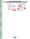
NOTE: Upon reassembly, apply a thin
layer of Lincoln E1868 (Dow Corning
340) heat sink compound to all bolted
electrical connections on the aluminum
heat sinks.
UPON REASSEMBLY, THE SCR
BRIDGE ASSEMBLY MUST BE ELEC-
TRICALLY ISOLATED FROM
GROUND.
_______________________________________
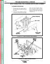
15. Place insulators between SCR
bridge assembly and the output
rectifier mounting bracket (see
Figure F.23). Check for electrical
isolation with an analog ohmmeter.
MINIMUM ACCEPTABLE RESIS-
TANCE TO GROUND IS 500,000
OHMS.
_______________________________________
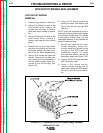
SCR OUTPUT BRIDGE REPLACEMENT
IDEALARC DC-1000
FIGURE F.23 - SCR Output Bridge Removal
F-51
CAUTION
CAUTION