


F-17
TROUBLESHOOTING & REPAIR
F-17
TEST DESCRIPTION
1. Disconnect main AC input power to
the machine.
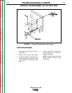
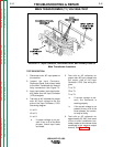
2. Inspect the Input Contactor,
Reconnect Panel, and primary leads
to the Main Transformer for loose or
faulty connections. See Figure F.3.
3. Apply input power, push start button,
and make sure the Input Contactor
(1CR) energizes.
4. Test with an AC voltmeter for proper
main AC input voltage to the line
side of the Input Contactor (1CR).
See wiring diagram.
L1 to L2.
L2 to L3.
L1 to L3.
a. If proper voltage is not pre-
sent in any or all of the three
phases, check input fuses
and leads.
5. Test with an AC voltmeter for
proper main AC input voltage from
the output side of the Input
Contactor. (1CR). See wiring dia-
gram.
T1 to T2.
T2 to T3.
T1 to T3.
a. If correct voltage is pre-
sent, the Contactor is
working properly.
b. If the correct voltage is not
present for any or all of the
three phases, the contac-
tor may be faulty.
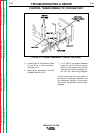
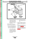
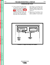
6. Test with an AC voltmeter for
approximately 60 VAC from each
of the six main transformer sec-
ondary leads to the common buss
connected to the negative output
terminal. See Figure F.4.
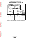
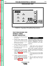
MAIN TRANSFORMER (T1) VOLTAGE TEST
IDEALARC DC-1000
Return to Section TOC Return to Section TOC Return to Section TOC Return to Section TOC
Return to Master TOC Return to Master TOC Return to Master TOC Return to Master TOC
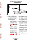
FIGURE F.3 - Input Contactor, Reconnect Panel, and Primary Leads to
Main Transformer Locations